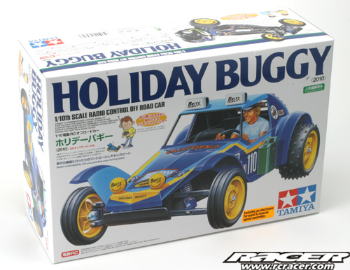
Build Report – Tamiya Holiday Buggy 2010
Tamiya seem to be on a big run of re-releases lately. In addition to the Buggy Champ and Sand Scorcher which have come out on their original chassis, I currently have sitting around my desk here at Racer, four recent kits – all of which the bodyshells have been seen on other chassis before!
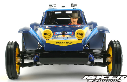
When many heard of the Holiday Buggy’s re-release there was excitement and disapproval in seemingly equal measure from Tamiya fans. Some vintage collectors liked the fact that they could have a retro styled basher on a modern chassis which was well priced and easy to get bits for. Others just abhorred the fact that it wasn’t on the original chassis…
What this Holiday Buggy is though is an ideal beginners RC car, absolutely perfect for those who have never built a kit, nor had a ‘proper’ RC car before. Here we will guide you through the build, showing you what’s involved and give you a brief running report. Watch out for the full Thrash Test in Racer magazine soon too!
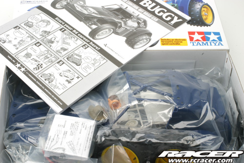
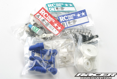
Looking at the kit, everything is clearly packaged. The screw bags are clearly marked and the instructions have full size drawings of the hardware in the relevant stages. This DF-01 is relatively simple and has only a few different sized screws in it making it easy for the beginner. The car kit also needs a 2 channel radio, battery and charger too, any good model store will supply you with these too.

Step 1 & 2
Step 1 simply tells you to charge your drive battery, Step 2 is where the screwing together of bits starts! This first part of the build attaches the front upper and lower wishbones to the front bulkhead.
Step 3
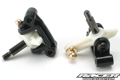
Moving on, Step 3 fixes the two steering knuckles to the C-Hubs using a threaded king pin.
Step 4
The uprights built in Step 3 are mated to the front end built in Step 2 along with the attachment of the front bumper.
 |
 |
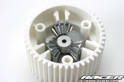
Step 5
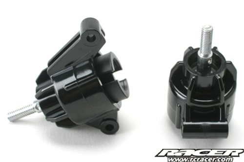
Now we move to the rear end. This stage deals with the assembly of the differential – a simple three planetary geared device. Make sure you use the supplied grease where indicated on all moving parts.
 |
 |
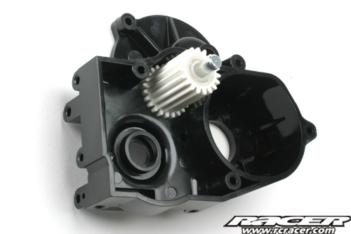
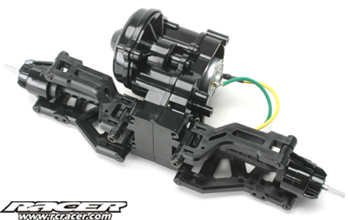
Step 6
The differential sits within the rear gearbox. Here we start building the gearbox by inserting the counter gear and shaft into one side of the casing.
Step 7
Here the differential is put into the gearbox and the other half mated up, closing the casing. Don’t forget the two BA11 outdrive bearings!
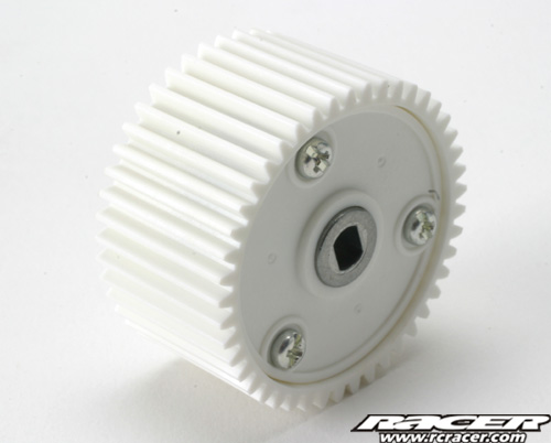
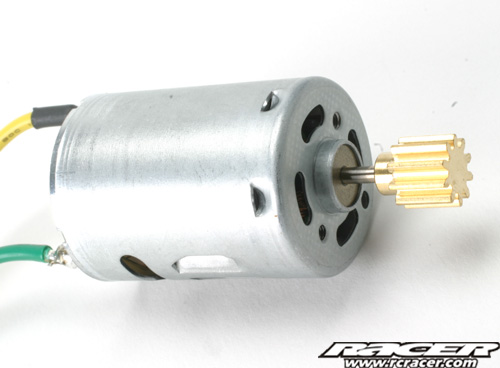
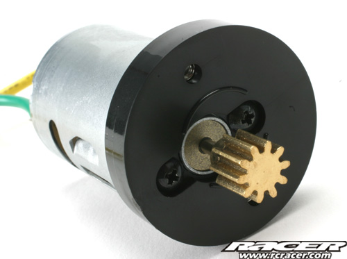
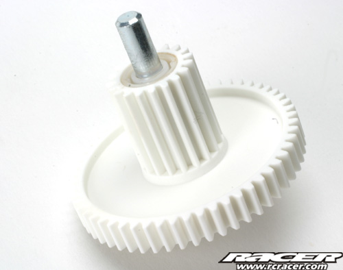
Step 8
The Holiday Buggy 2010 is powered by a 380 sized motor, just like the original kit from 30 years ago. Here the motor is attached to an adaptor plate and also the gearbox spur gear is assembled onto its shaft.
 |
 |
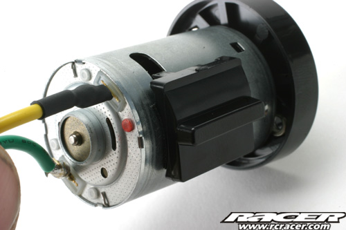
Step 9
Now the motor and spur gear are put into the gearbox. Make sure to tape the small plastic moulding to the motor where instructed as this reduces stress on the motor adaptor plate during running.
 |
 |
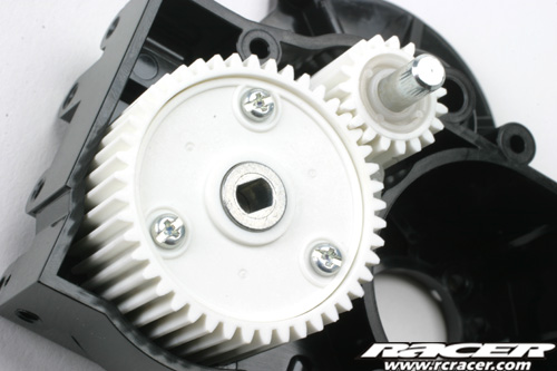
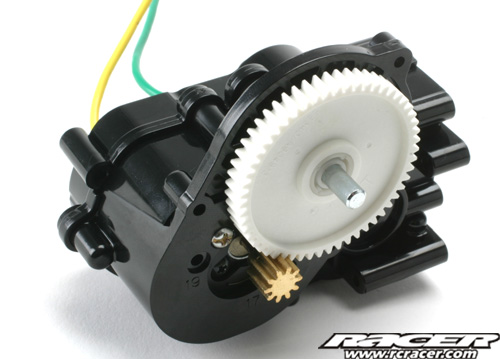
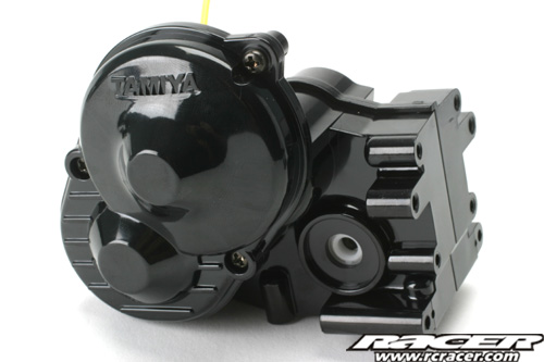
Step 10
The final stage of the assembly of the actual gearbox sees the cover attached over the spur gear.
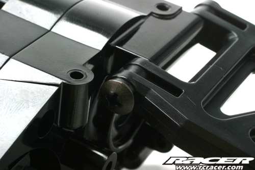
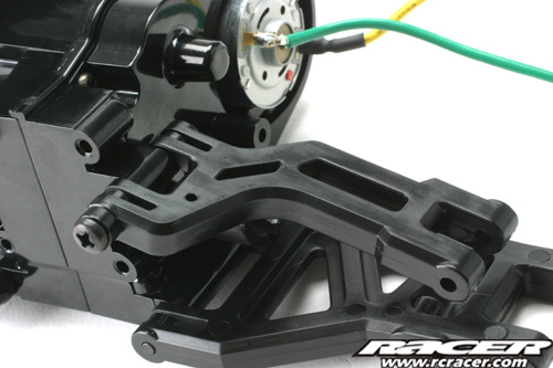
Step 11
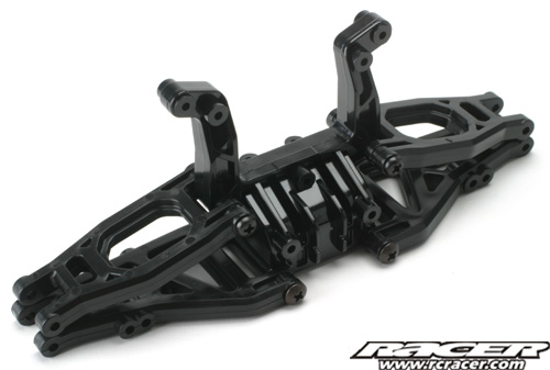
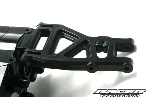
Step 11 sees us move to the rear suspension. The two lower rear wishbones are attached to the gearbox at this point.
 |
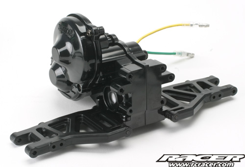 |
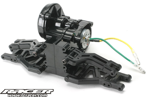
Step 12
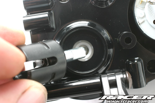
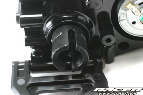
Here the two upper wishbones are attached. Also the outdrives are inserted at this point. Make sure you get the flats on the outdrive aligned with the gears in the differential in the ‘box.
 |
 |
 |
 |
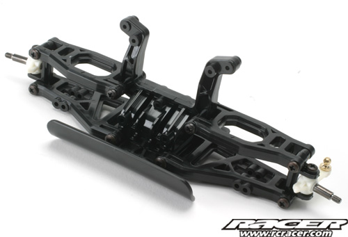
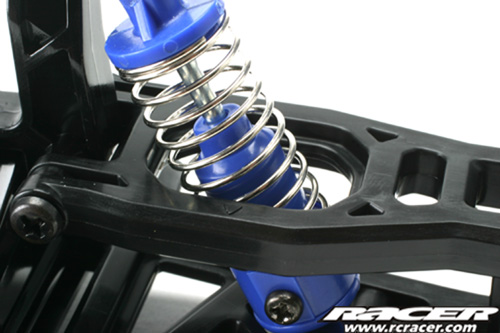
Step 13
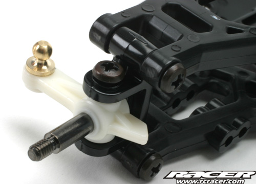
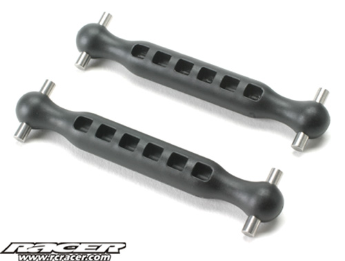
Now the rear suspension comes together. The rear uprights have their bearings and shafts inserted now and these are then attached to the wishbones, taking in the two chunky moulded plastic driveshafts too.
 |
 |
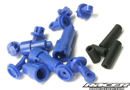
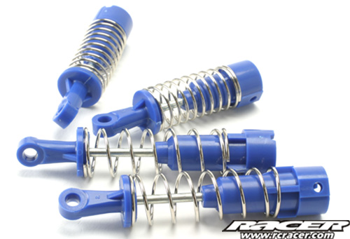
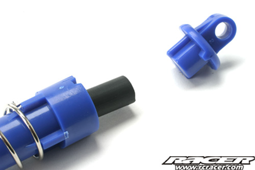
Step 14
Time to open up parts bag B. Here we build the shock absorbers. Make sure you use the right shafts and shock body mouldings (F2 & F3) for the front and rear as they are different lengths. The shock shafts are hard to screw into the shock bottoms (Part F4). Use a little of the grease supplied on the threads of the shafts and this makes it much easier.
 |
 |

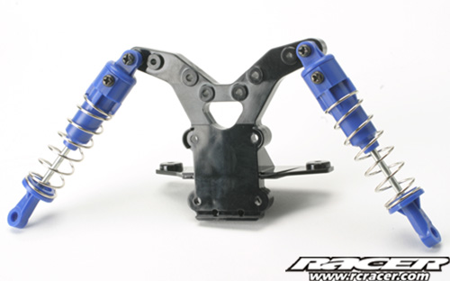
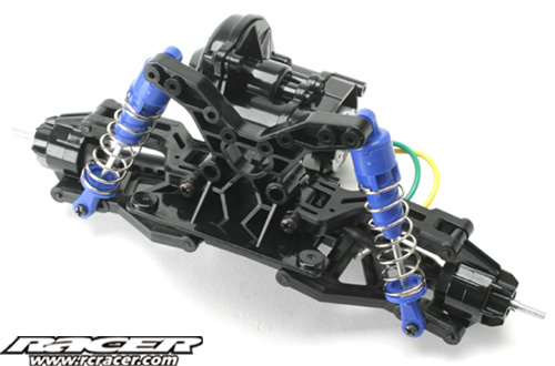
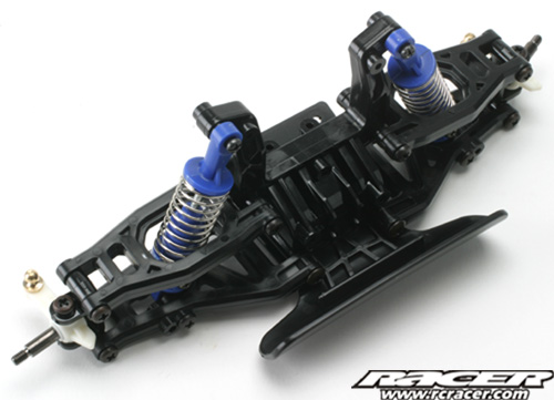
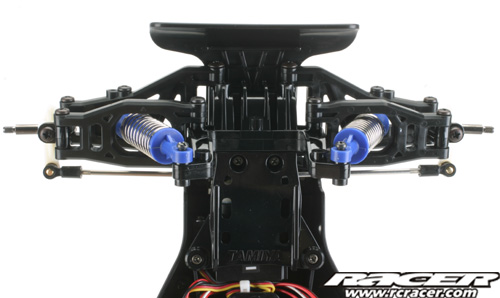
Step 15
The rear shocks are now mated to the gearbox and rear suspension after first being attached to the moulded plastic shock tower.
 |
 |
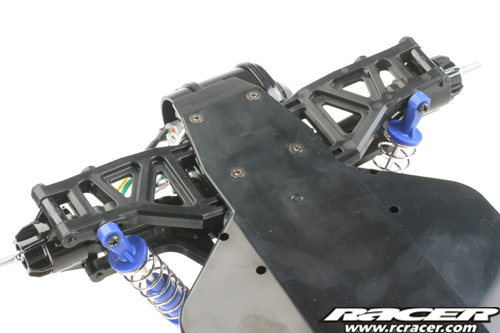
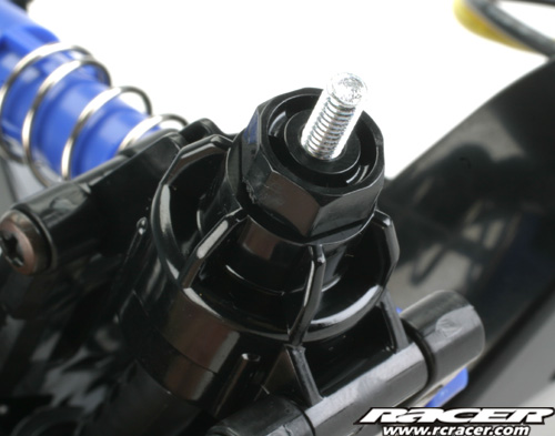
Step 16
Here the front shocks are attached. Make sure to notice that these are attached upside down compared to the rears. Also make sure you don’t miss out the small BB14 bushing that goes in the bottom of the shock.
 |
 |
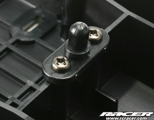
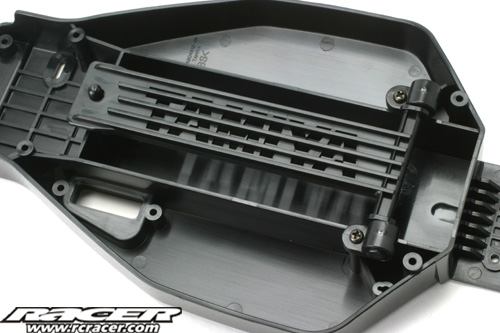
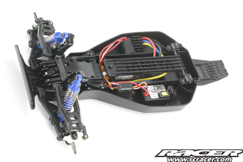
Step 17
Its time for the bit that goes in between the front and rear ends….the chassis! Here the hinged battery holder and attachment point are screwed to the chassis tub.
 |
 |
Step 18 & 19
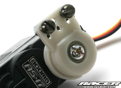
Step 18 shows you what radio equipment you need for the Holiday Buggy. We used an Acoms Techniplus set, perfect for the car. Step 19 sees the steering servo saver built. The correct part for the Acoms servo is clearly marked in the instructions.

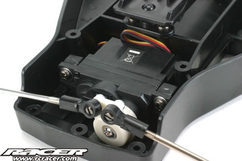
Step 20
It is important to centralise your steering servo before installing it into the chassis or the car may not run in a straight line. This step shows you how to do this. And attach the steering servo saver.
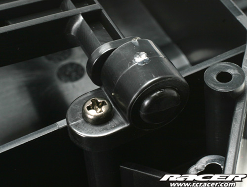
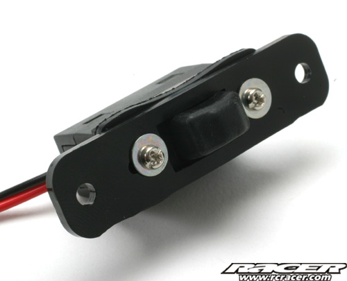
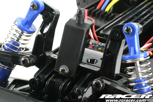
Step 21
Now we attach the servo mounts and also the rubber cover and plate to the switch on the kits TEU-104BK electronic speed controller. As ours it a UK kit, it comes with an ESC although the inclusion of this may vary from country to country.
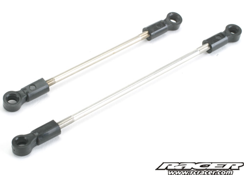
Step 22
This stage deals with the build of the steering rods. Precise drawings are given in the manual at actual size to make it easy for you to achieve the correct lengths.
 |
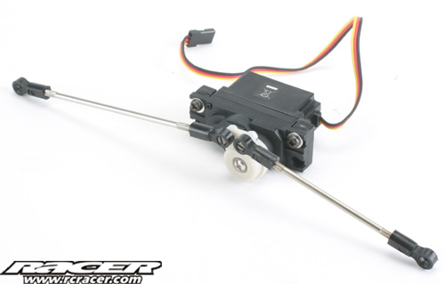 |
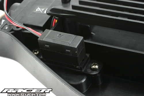
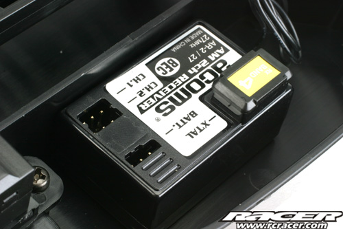
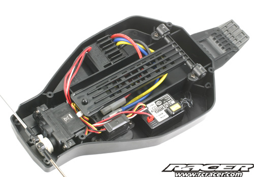
Step 23
Time to install the RC gear in the chassis. The servo and switch are screwed into position while the ESC and Acoms receiver are attached with the double sided tape supplied in the kit.
 |
 |
 |
 |
 |
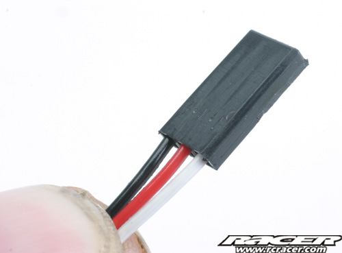 |
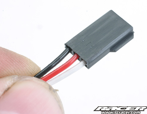
We had to trim the speed controller connector tab so it fitted into our Acoms receiver.
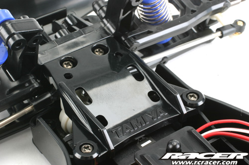
Step 24
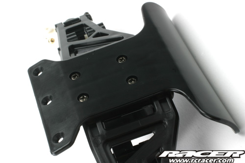
Here we attach the front end to the chassis. It is held on with three countersunk screws underneath and a plate attached by four screws on top making it good and strong. Make sure you snap on the steering links to the upright’s ball connectors here too.
 |
 |
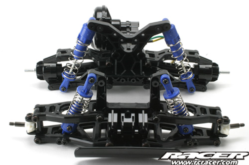
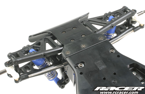
Step 25
Now for the rear end. The sub-assembly is fixed to the main chassis with six screws, again countersunk on the underside. It’s really starting to come together now!
Step 26
This stage is a sort of ‘systems check’, showing you how to make sure your steering setup is correct.
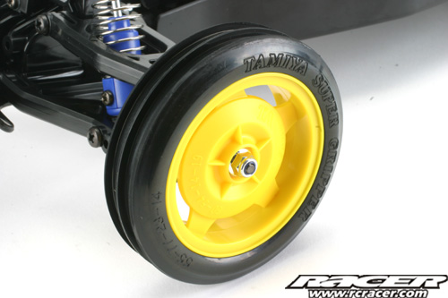
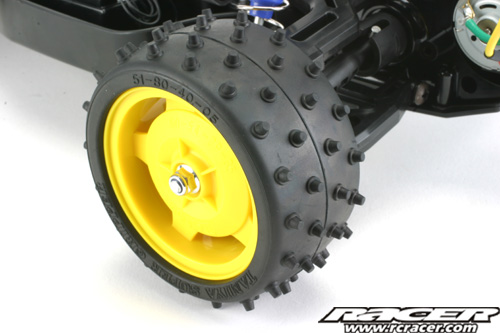
Step 27
We are nearly finished on the chassis now. Here the wheels and tyres are attached. They are assembled in the box, just bolt them on as instructed! Don’t forget to grease the front avles as shown though…
 |
 |
 |
 |
Step 28 & 29
Step 28 shows you how to install the drive battery, Simples. Step 29 shows you how to tidy your wiring. We had already done this though when we installed the radio earlier…
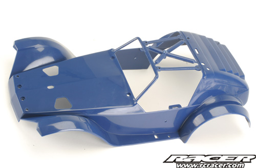
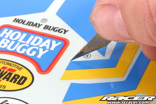
Step 30
Bodyshell time and good news – the instructions say that the body cannot be painted! One less job! This stage shows the sticker positions. The stickers are not cut out on the sheet so you will have to cut them out using a knife or scissors, whichever you find easier.
 |
 |
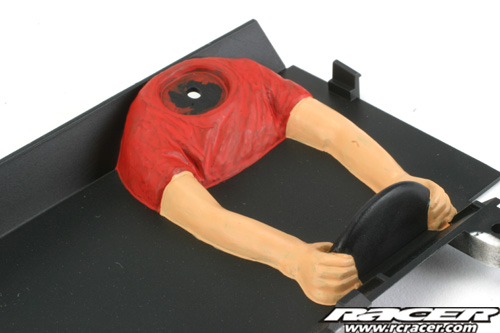
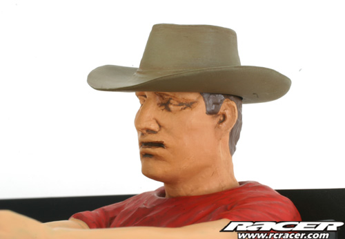
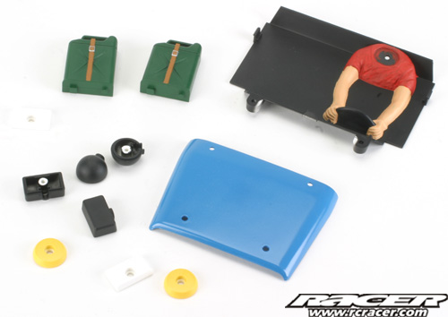
Step 31
There are plenty of small parts that need painting on the Holiday Buggy. The driver figure needs painting but the head and hat come pre-finished. The paint finish here is good but the drivers face has a brown wash over it making him look like he’s been snuffling for truffles…
 |
 |
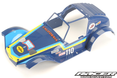
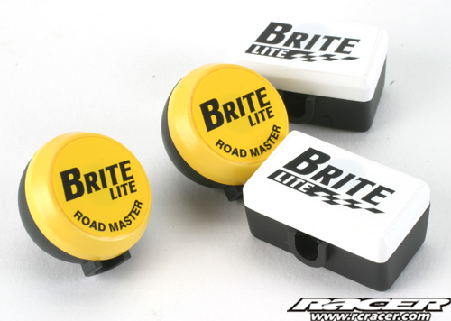
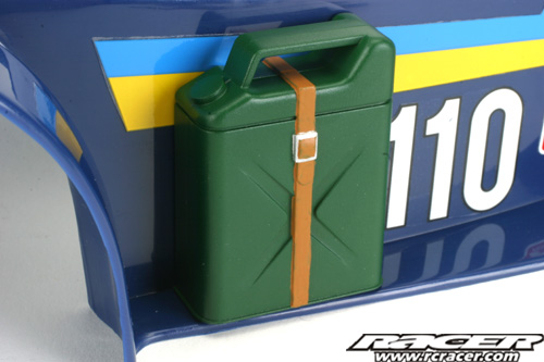
Steps 32 & 33
Here the rest of the detail parts such as the spot lights and jerry cans are painted up and attached to the body. As Tamiya TS paints are currently unavailable in the UK, I used Halfords Ford Electric/Monza Blue for the roof panel.
 |
 |
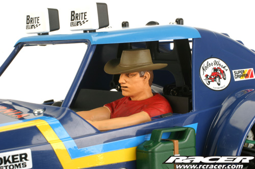
Step 34
The bodyshell is finished with the attachment of the driver figure to the main shell.
Step 35
The rear body mount is attached to the rear shock tower.

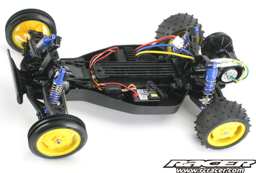
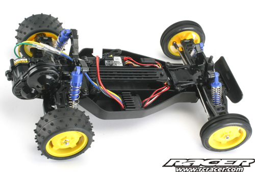
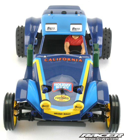
Step 36
FINISHED! The bodyshell is mounted on the chassis, all done – time to run it!
Build Conclusions
This kit goes together very easily as you would expect, even a complete novice could do it in a couple of evenings. And that I feel is the target market of the Holiday Buggy. For a long time, there hasn’t been a beginners kit, everything is RTR now…if you are looking to get into ‘proper’ RC cars, this is ideal, whatever your age.
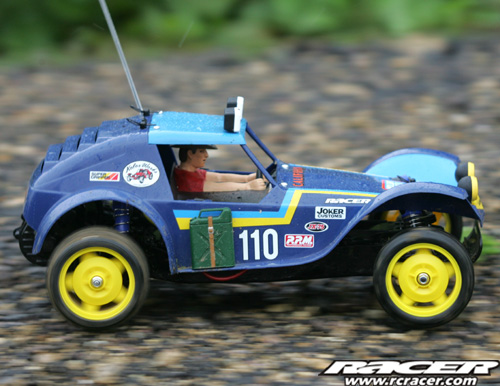
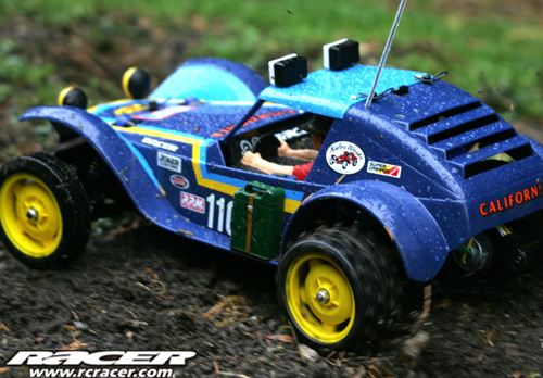
Run It!
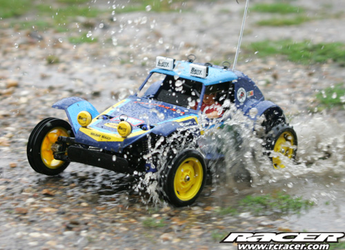
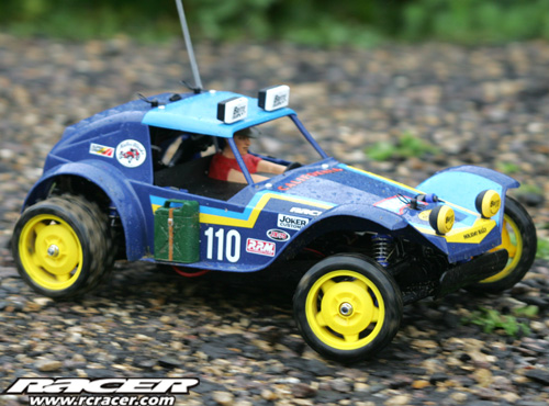
We don’t recommend running your Holiday Buggy through puddles, it does make for cool pictures though! Do as we say, not do as we do…
We will leave the main running report for the Thrash Test in Racer magazine. Briefly though, the 380 motor means that it won’t break the land speed record but is fast enough to be fun.
The cars friction dampers mean that it bounces a lot on rough ground, just like the original but the good thing is that the 2010 version is a whole load stronger!
Check out our on-board video here for a drivers eye view!!
{gallery}gallery/aug10/tamhbweb{/gallery}