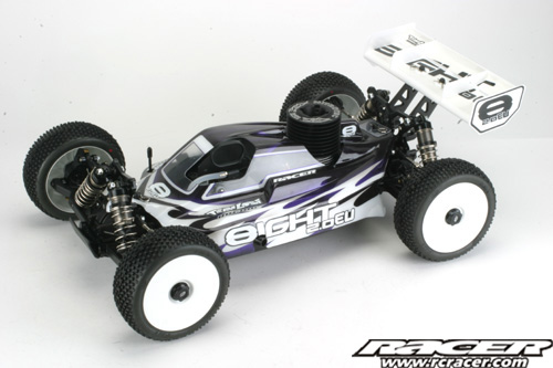
LIVE BUILD – Losi 8IGHT 2.0 EU – Updated 11.44am Finished!
Hello, good morning and welcome to our live build of the Losi 2.0 EU edition. This buggy has seen great success since its launch seeing success in Europe and the UK at BRCA Nationals thanks to drivers like Darren Bloomfield.
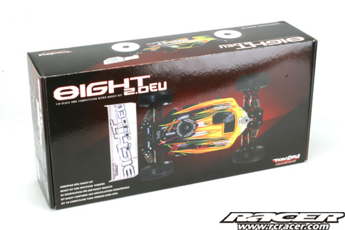
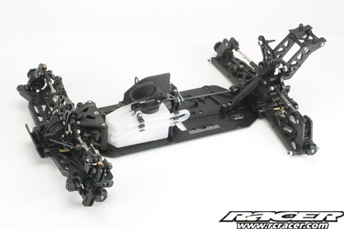
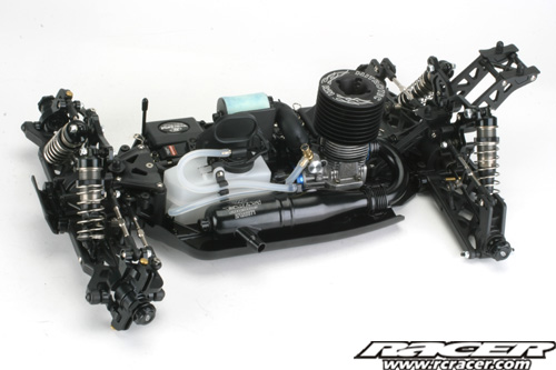
Firstly, heres a few shots of what you get for your hard earned money, the short answer being a lot! The 2.0 EU is one of the most concise and well thought out 1:8 buggy kits out there.
 |
 |
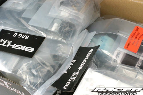
| The kit comes with each construction stage packed with the parts in separate, clearly labelled bags |
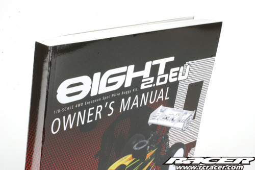
Check out the thickness of the build manual! This includes several different languages and full setup guide and info. |
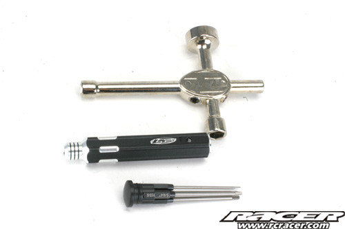
Losi also include some quality tools with the kit. In addition to the usual wrench, there is also an allen driver which includes driver tips to build the car.

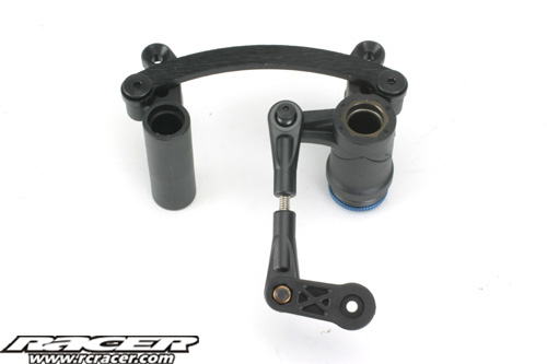
Steps A-01 & A-02 (10.23am)
The build starts with the steering assembly. A-01 is just building the link from the servo to the steering bellcranks while A-02 deals with the servo saver and drag link assembly to the bellcranks.
 |
 |
Step A-03 (10.44am)
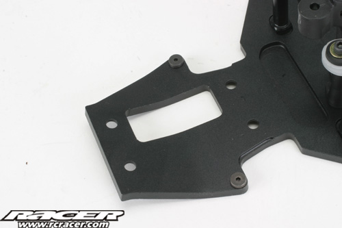
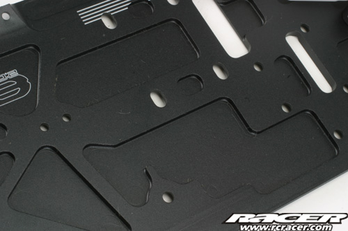
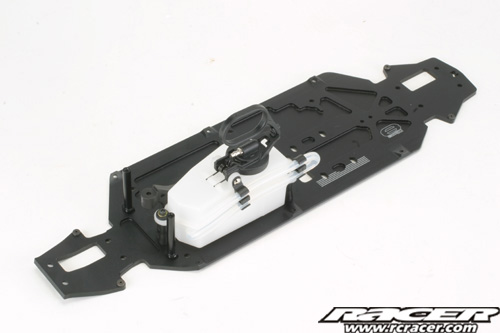
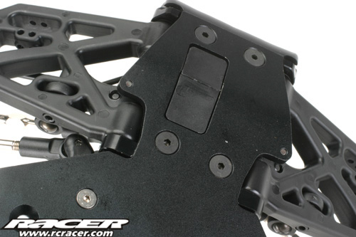
Moving on….next we crack out the nicely milled main chassis plate and start by bolting on steering posts, the front chassis brace and the fuel tank.
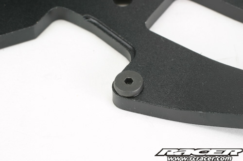
The chassis plate has neat little steel screw inserts where the suspension downstop screws touch to stop the droop screws eating into the alloy plate.
 |
 |
| The front of the chassis has kick-up incorporated into the plate. | Chassis has been milled in areas to reduce weight and aid flex. |
 |
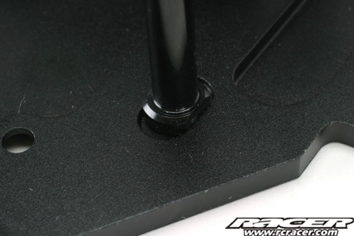 |
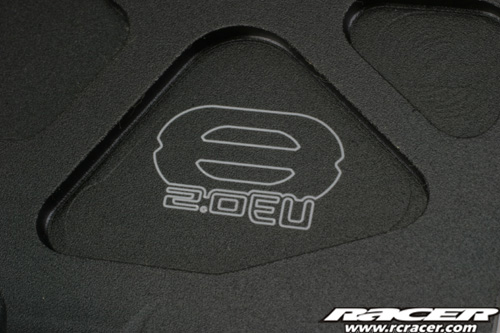
| 8IGHT 2.0 EU branding features on the chassis plate. | The steering posts locate in a milled part of the chassis making tightening easy. |
 |
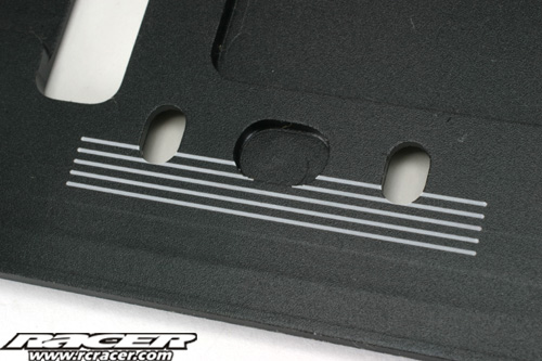 |
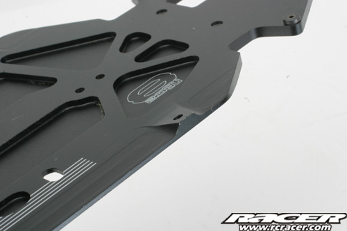
| More milling out on the chassis plate. | Neat marks etched into the chassis aid engine alignment. |
 |
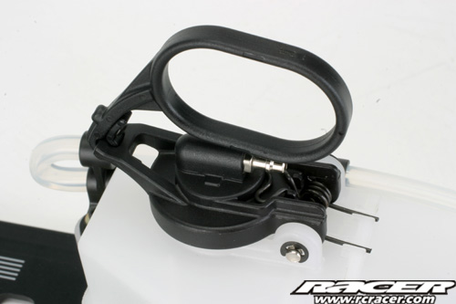 |
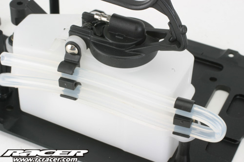
| Fuel tank has neat clips so tubing routing is kept tidy. | Also the tank comes complete with a pull handle for refuelling. |
Build stage A-03 complete!
Step A-04 (10.54am)
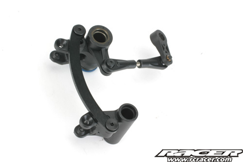
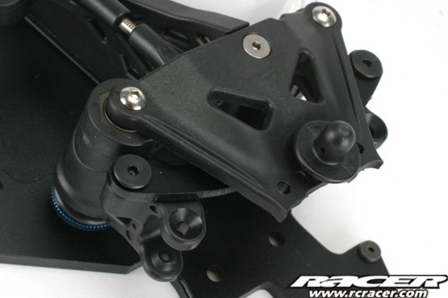
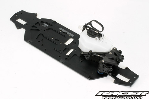
Next, the steering assembly built up in Steps A-01 & A-02 is attached to the chassis.
 |
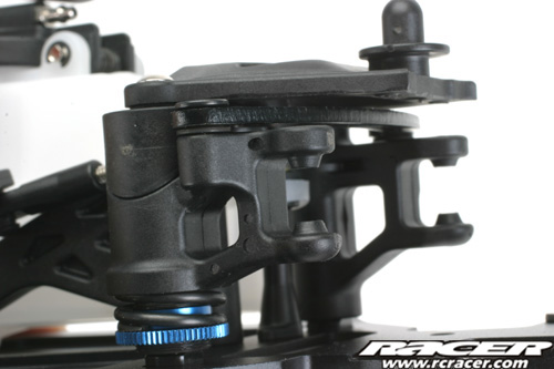 |
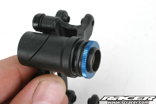
| The 8IGHT 2.0 EU has a plastic moulded steering top brace and aluminium drag link. | Servo saver adjustment is at the bottom near the chassis plate. The steering bellcranks move on four ballraces. |
Step A-05 (10.58am)
No actual building in Step A-05, the manual just shows a completed drawing of the chassis assembly so far…
Step B-01 to B-03 (11.16am)
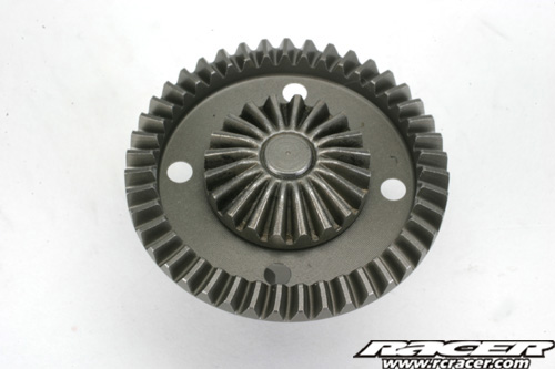
With many 1:8 buggy kits, assembly starts by building all three differentials at once. However, the Losi takes a different approach and now we start at the front of the car, building the front diff only.
 |
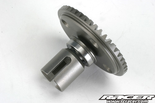 |
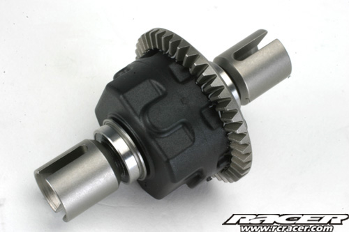
| The front differential assembly is pretty conventional using steel gears. | Steel outdrives are also present. Make sure you put the flanged diff bearing on round the right way! |
 |
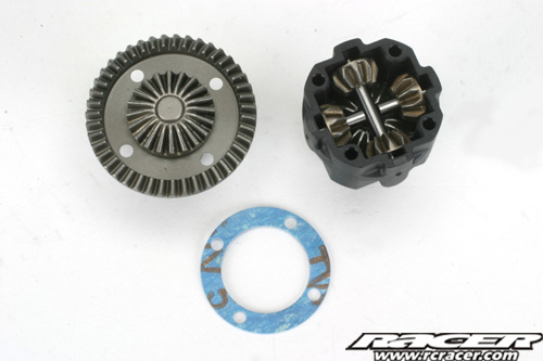 |
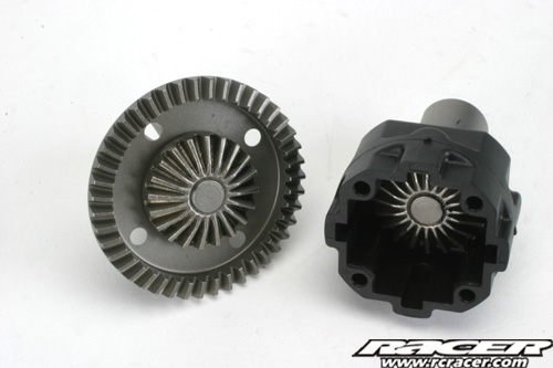
| Step B-02 deals with the assembly of the other side of the diff case which has a plastic housing. | In B-03, the four steel planetary gears are inserted with their cross shafts. |
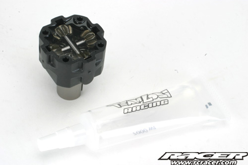
Losi provide some 7000WT oil for filling the front diff, a popular choice on the setup sheets of various team drivers.
 |
 |
The diff oil is filled to just above the planetary gears then screwed together with the sealing gasket. Unusually, the 8IGHT 2.0 EU uses Imperial American screws throughout apart from on the diffs which use metric 3x12mm screws.
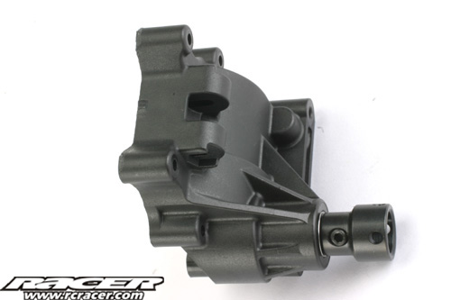
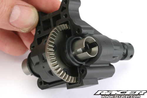
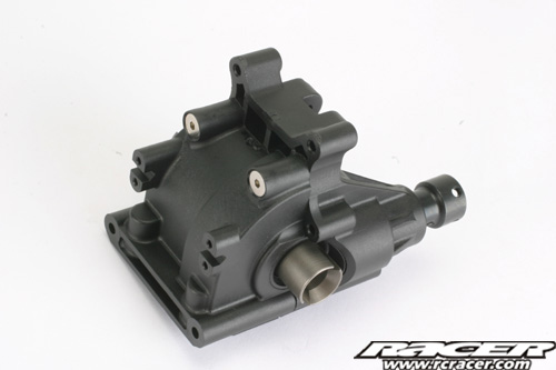
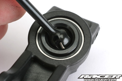
Step B-04 (11.32 am)
Now, the differential and input shaft are installed into the front gearbox casing.
 |
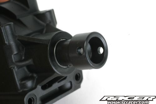 |
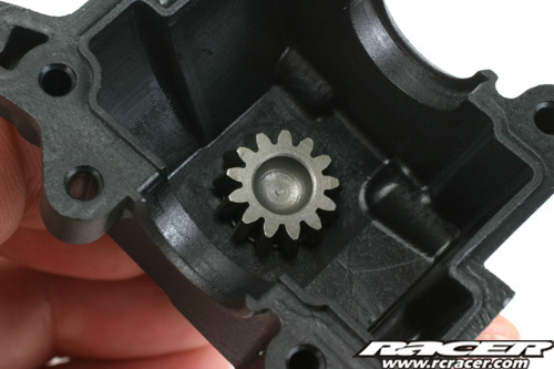
| The one piece input gear and shaft installed. | Gearbox input CVD Cup. |
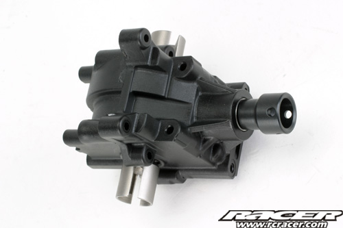
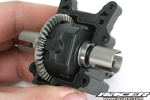 |
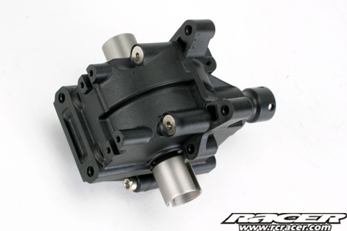 |
| Differential inserted into the casing. | Screws tightened and front gearbox casing assembly complete. |
Step B-05 (11.42am)
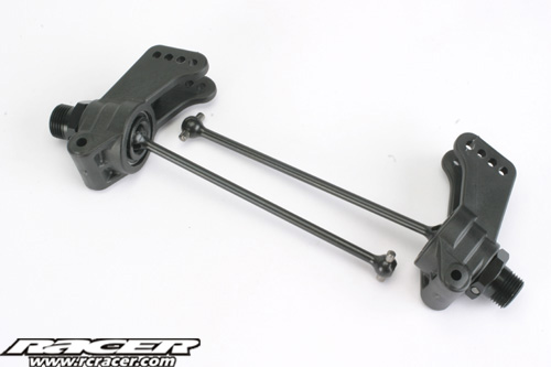
Assembly moves onto the machined aluminium front steering knuckles and driveshafts.
 |
 |
| The CVD driveshafts use the inner bearing in the steering knuckle to retain the drive pin. | The nice Losi wheel nuts have serrations to positively grip the plastic on the wheel. |
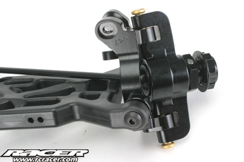
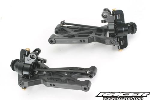
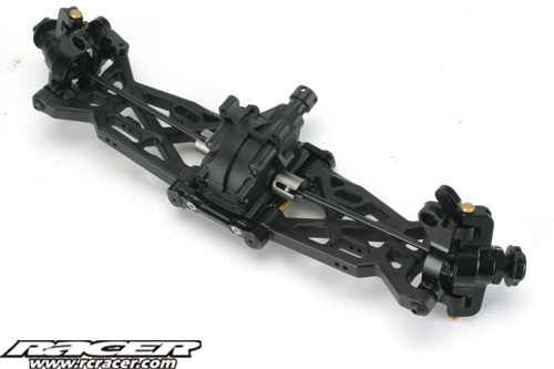
Step B-06 (11.54am)
Next, the front steering knuckles are assembled to the aluminium hub carriers and front suspension wishbones. Both left and right assemblies are built in the same construction stage.
 |
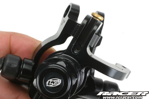 |
| The machined alloy hub carriers are 12 degree parts and make for a very strong front end. | The Titanium Nitride coated king pins are retained by set screws in the steering knuckles. |
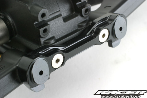
Step B-07 (12.03pm)
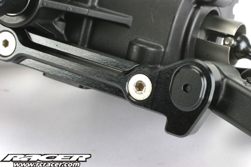
The front wishbones are now brought together with the front gearbox casing. The hinge pin retainers are machined aluminium and have adjustment cam inserts to alter the hinge pin geometry.
 |
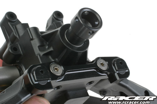 |
| The front hinge pin holder has adjustment cam 0 inserted as stock… | …as does the rear holder too. Both hinge pin holders are nicely machined from aluminium and anodised black. |
The hinge pins are titanium nitride coated parts.
Step B-08 (12.11pm)
The Losi 8IGHT 2.0 EU comes with anti-roll bars as stock. Step B-08 deals with the assembly of the front bar.
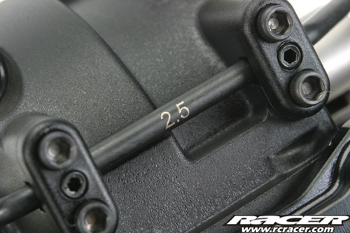
The stock front bar is a 2.5mm part. Alternatives are provided in the kit though, more on this later…
 |
 |
| The drop links to the wishbone are one-piece moulded parts. | The assembled anti-roll bar on the front suspension. |
Step B-09 (12.23pm)
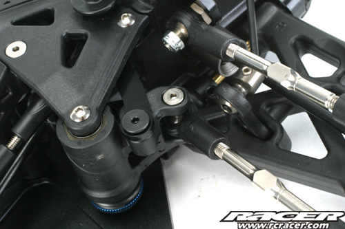
Onto the front shock tower and camber link assembly. This is all built up and attached to the front gearbox in one stage, B-09.
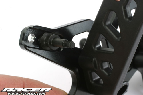
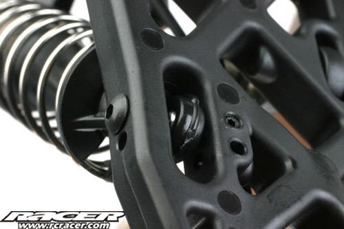
These front shock fixings are a very neat touch. They enable you to change the positioning in the shock tower by removing only the retaining nut behind the tower.
 |
 |
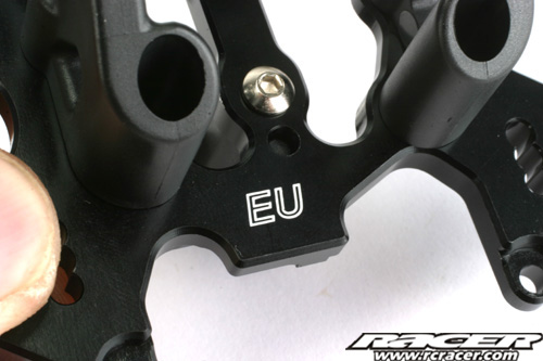
| EU branding again features on the machined aluminium front shock tower unique to the EU kit. | The front tower is milled out in key areas to save weight. Black anodised finish looks classy. |
Step B-10 (12.29pm)
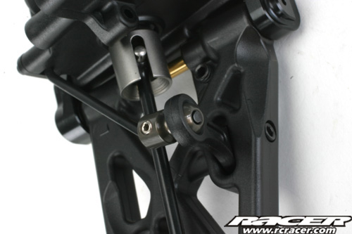
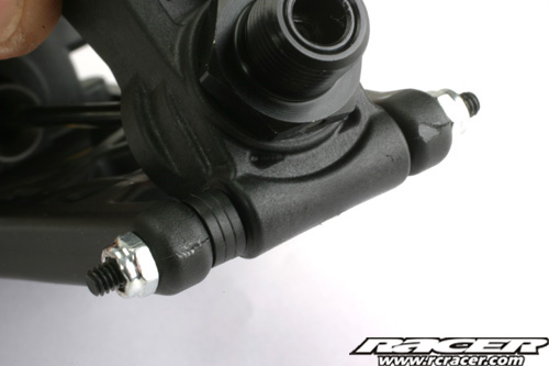
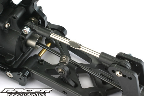
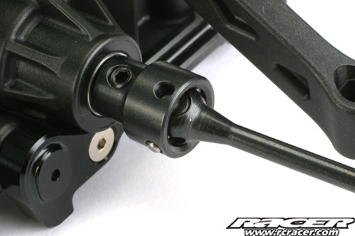
Step B-10 deals with attaching the CVD centre driveshaft to the front gearbox. The drive pin is retained by a set screw and there is also a flat on the pin for positive location.
Step B-11 (12.36pm)
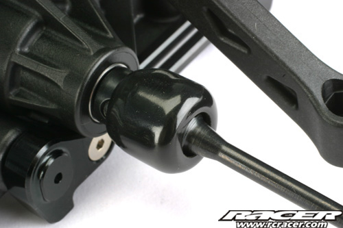
Here, the steering turnbuckles are added and CVD gaiter slid over the driveshaft joint.
 |
 |
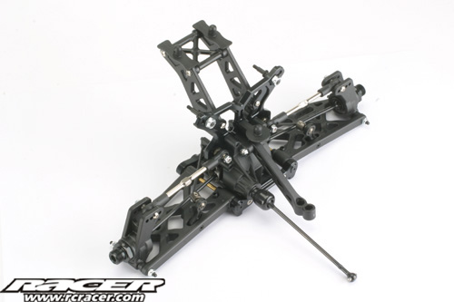
Steps B12 & B13 (12.50pm)
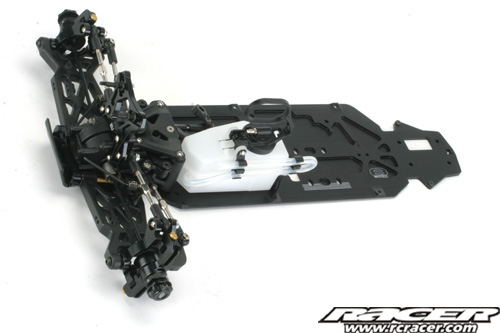
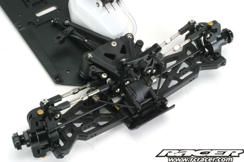
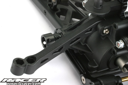
Step B-12 attaches the front gearbox and suspension assembly to the chassis plate we worked on earlier with B-13 just being an overview of the completed buggy to this stage.
 |
 |
| The steering turnbuckles are attached to the bellcranks at this point. | The plastic gearbox casing locates in a cut-out in the chassis plate. |
Step C-01 To C-03 (2.12pm)
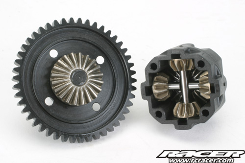
Moving to the middle of the 8IGHT, now we move onto the centre differential, brakes and mounting. Firstly the centre diff.
 |
 |
| The centre diff uses the same internal gears as the front and rear units. | The 8IGHT 2.0 EU comes equipped with a steel 46 tooth spur gear. |
The centre differential is filled with the kit supplied 5000WT oil.
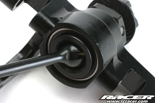
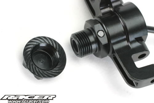
Step C-04 (2.24pm)
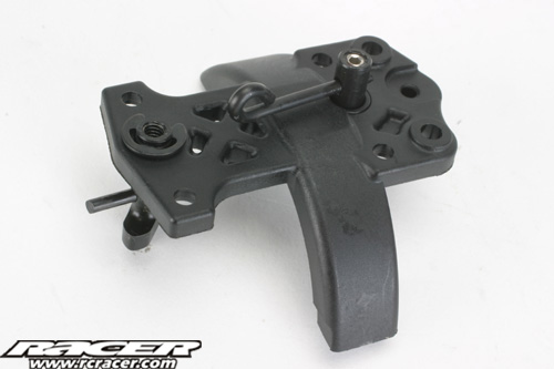
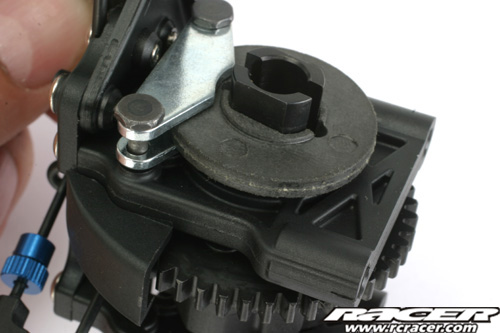
The top brace for the centre diff mounting is next on the agenda, step C-04 taking in the assembly of the brake cams which have a metal bearing to act on in the plastic top plate.
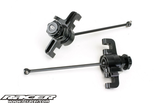
Step C-05 (2.32pm)
Onto the throttle and brake linkages. The servo horn is a kit supplied composite item that has inserts for different makes of servo. Be careful not to overtighten the linkage screws otherwise they will bind.
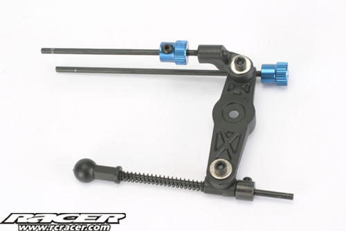
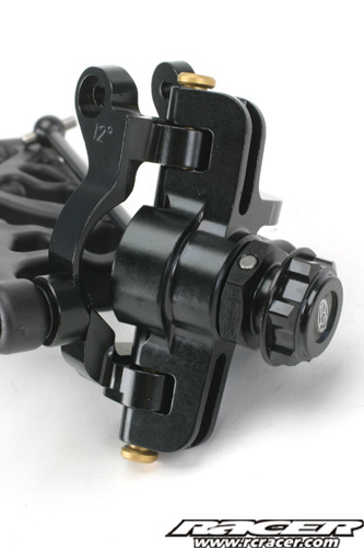
Step C-06 (2.41pm)
The throttle/brake linkage is now connected to the centre diff mount top plate. The brake action is made to feel more progressive by the small pieces of fuel tubing on the linkage. The lower brake linkage has the adjuster on the end of the rod making changes easier, a little detail but it shows some thought from Losi in this area.
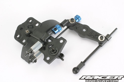
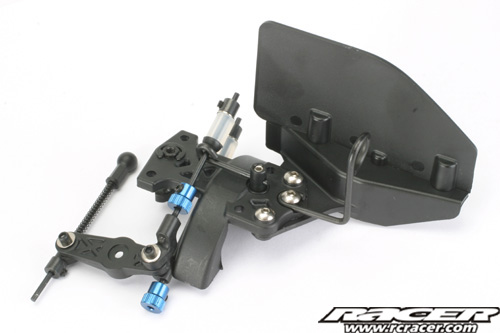
Step C-07 (2.46pm)
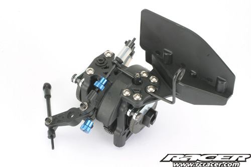
The final additions to the top of the centre differential brace are the fuel tank splash guard and the air filter support. The latter is a wire piece that holds the front of the filter, reducing the chances of heavy knocks dislodging the filter from the engine.
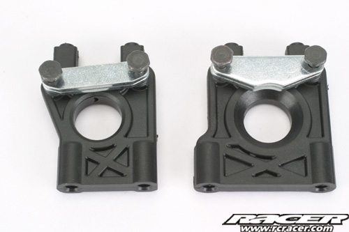
Step C-08 (2.53pm)
Step C-08 moves to the centre differential support mouldings. The brake pads are fixed to these on sliding brake shoulder screws. The pads are identical front and rear. Make sure though you get the slightly slotted holes in the pads in the right places though so the pads ‘float’ properly.
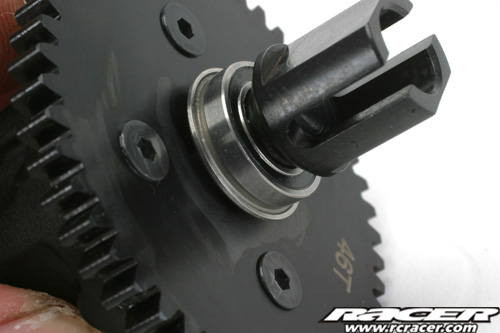
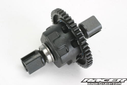
Step C-09 (2.59pm)
Now the centre differential is assebled into its housing with the brake discs ready for attachment to the chassis.
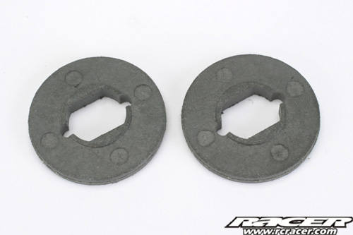 |
 |
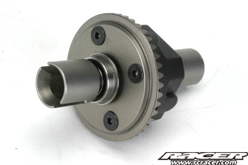
| The front and rear brake discs are moulded composite parts and the same for the front and rear of the buggy. | Unusually, the 8IGHT uses a single piece differential support, unlike the horizontally split parts on most competition nitro buggies. |
Step C-10 & C-11 (3.04pm)
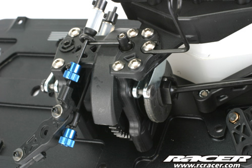
Finall for the C-steps, the centre differential housing/assembly is screwed to the chassis.
Step D-01 to D-03 (3.17pm)
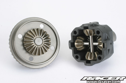
Onto the rear of the 8IGHT. This starts with the rear differential.
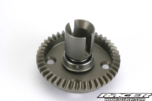
Step D-01 assembled the main gear side of the differential. Those unfamiliar with a Losi 8IGHT may think that the teeth for the gear are on the wrong side…a foolish thought for which small children will point and jeer at you. As will I. All will become clear soon…
 |
 |
| Again, the diff uses the same internal gears as the other two at the front and centre. | The completed rear diff filled with the kit 2000WT oil. |
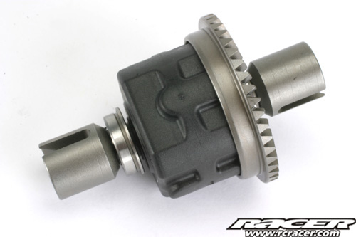
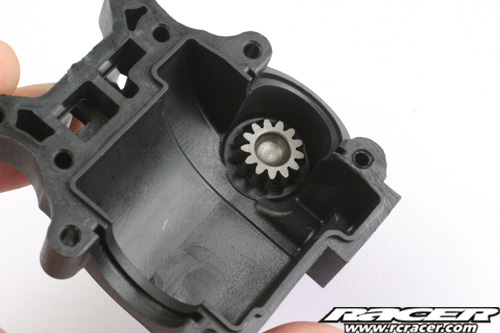
Step D-04 (3.37pm)
Time to assemble the rear differential into the gearbox housing. The 8IGHT uses an offset input shaft, hence the diff gear teeth on the other side, which allows the centre driveshaft to run off centre on the chassis plate. This allows the engine to be moved more towards the middle for improved side-to-side balance.
 |
 |
| This shot shows the offset input shaft. | Slotting the rear diff in place. Make sure to put the correct bearing shims in place as shown in the manual. |
The rear differential installed snugly in the gearbox housing.
Step D-05 (3.45pm)
The rear hubs and driveshafts are built in Step D-05. These are handed left and right so pay attention to the parts used, all clearly marked in the instructions and on the parts themselves.
 |
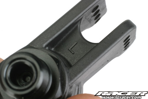 |
| As with the front end, the CVD pin is held captive by the unner bearing. | The moulded plastic rear hubs are marked L and R. Make sure you get the right ones on the right side! |
Step D-06 (3.57pm)
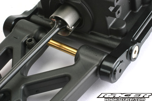
The rear hubs are now attached to the wishbones which are then, in turn, hung off the gearbox by more aluminium hinge pin holders via titanium nitride coated hinge pins.
 |
 |
| The aluminium hinge pin holders again have inserts to adjust the hinge pin position. | The outer hinge pins have spacer shims so the wheelbase length can be changed. |
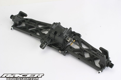
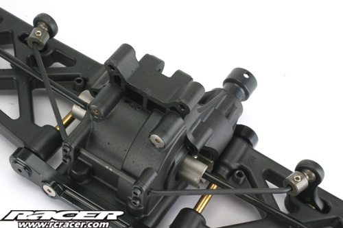
Step D-07 (4.07pm)
As with the front end, a rear ant-roll bar is stock equipment. D-07 deals with its attachment to the gearbox and the wishbones.
 |
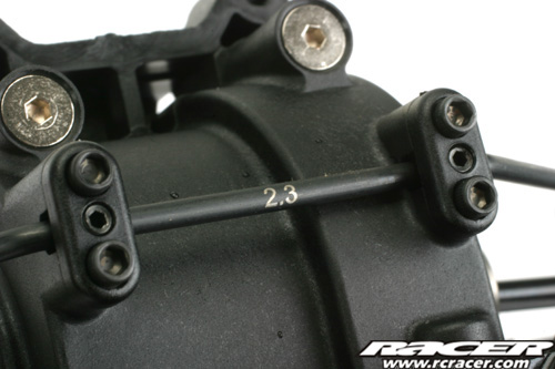 |
| The rear anti-roll bar installed. | The back end receives a 2.3mm thick bar. |
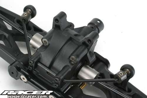
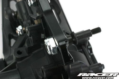
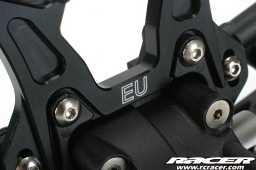
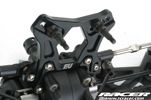
Step D-08 (4.25pm)
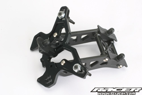
The rear shock tower and wing support is next on the agenda. Again a milled aluminium tower features with plenty of setup options for the shock and camber link positions. The wing support however is not adjustable and uses plastic cross-braces. However, the Losi uses nice, long screws here so strength shouldn’t be an issue.
 |
 |
| Unique EU rear aluminium shock tower is also branded. | Those clever top shock mounts also feature on the back end. |
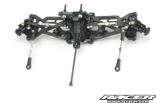
Step D-09 (4.30pm)
Now we see the rear shock tower assembly come together with the rear gearbox and also the rear composite plastic chassis brace get added too.

Step D-10 (4.39pm)
This simple step adds the rear turnbuckle upper links.
Step D-11 (4.47pm)
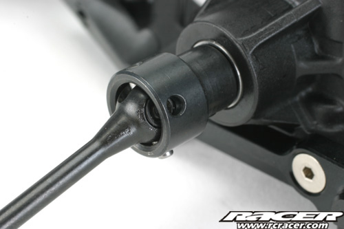
The last stage of the rear gearbox assembly sees the CVD centre shaft attached. Make sure to use the grease and threadlock where instructed for reliability and longevity of the parts.
 |
 |
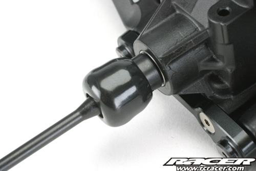
| As with the front, the CVD centre pin is retained by a set screw… | …and a neat rubber dust boot also covers the completed joint assembly. |
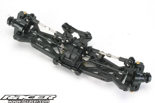
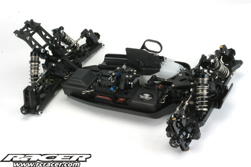
Steps D-12 & D-13 (4.53pm)
The last of the D’s sees the rear end attached to the chassis. Make sure you locate the centre driveshaft into the drive cup on the centre diff or you will have to take the rear end off again!
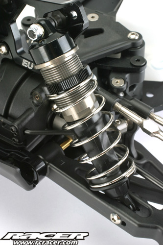
Step E-01 (5.14pm)
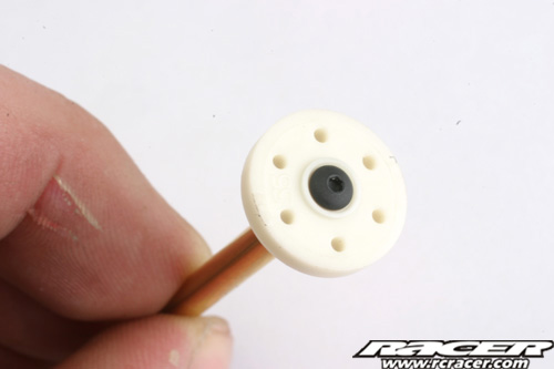
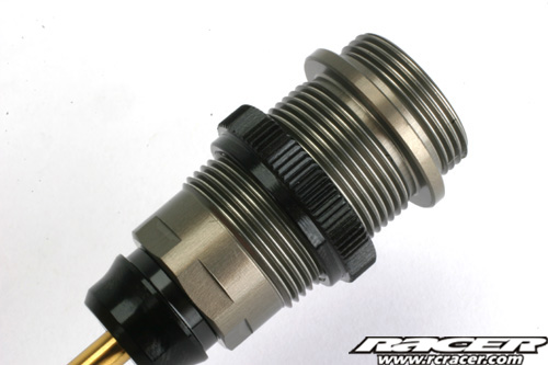
Next the build moves onto the shocks. Follow the instructions and you ill have silky smooth dampers. Oil provided in the kit is 37.5WT for the front end and 32.5WT for the rear. Both front and rear shocks use the same No. #55 pistons.
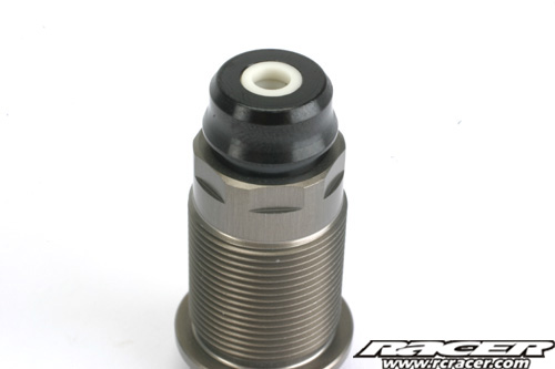
Shock bodies are hard anodised and threaded parts. The bottom seals are held in place by a threaded cap. There are two O-rings for sealing.
 |
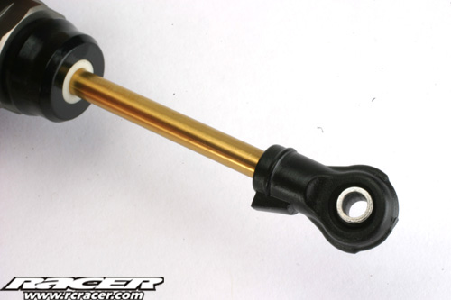 |
| No. #55 pistons are supplied for the front and rear as the stock setting. These are held to the pistons with small screws. | Titanium nitride coating features on the front and rear shock shafts. |
 |
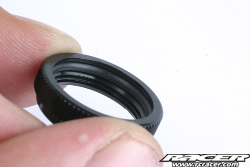 |
| Threaded adjusters allow for infinite ride height changes and precise setting. | The ride height collars have an O ring inside to help them maintain their settings. |
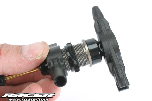
Losi include these neat plastic tools in the 8IGHT 2.0 EU kit to help you tighten the shock caps fully.
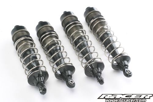
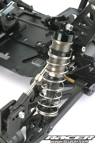
Step E-02 (5.19pm)
This next stage is simply slipping the rubber shock shaft boots over the bottom of the shocks and attaching the springs and retainers. I found that a small drop of oil on the ball joint helped to ease the rubber boots in place. The bottom shock collars align with a locating key on the ball joint to help avoid them becoming dislodged on rough tracks.
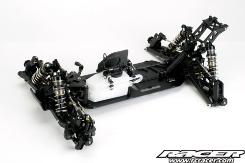
Steps E-03 to E-05 (5.29pm)
Now the shocks need attaching to the buggy. Pay close attention to the instructions as each and of the 2.0 has a black and a silver screw which are handed to the left and right of the car. This is to help stop the shock bottoms coming undone in use.
 |
 |
 |
 |
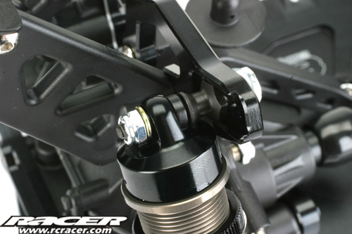
| Rear shock attached to the aluminium tower. | Notice the small set screw in the wishbone to help secire the bottom mounting screw. |
Steps F-01 to F-07 (10.00am)
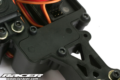
These seven steps deal with installing the chassis side guards and radio system into the radio plate and box.
 |
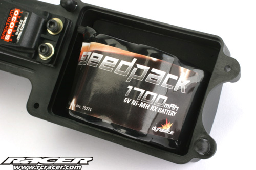 |
| Losi offer the option of fitting a switch or a blanking plate to the radio box. We went with the latter choice. | We used a Dynamite 1700mAh pack to power the radio. Two different lids for ther battery case are provided to accomodate different packs. |
 |
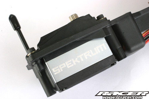 |
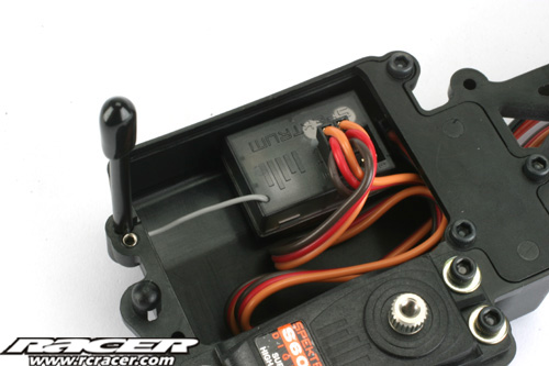
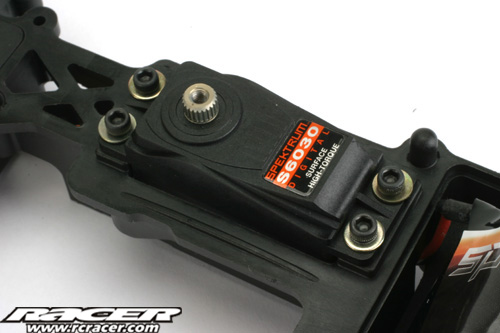
| The little Spektrum reciever looks a little lost in the receiver box! | Unusually there is no guide for installing Spektrum servos in the EU instructions. They need no spacers though. |
 |
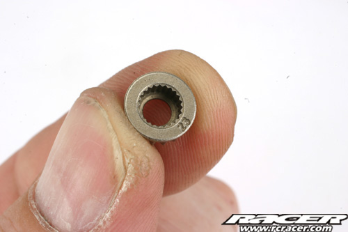 |
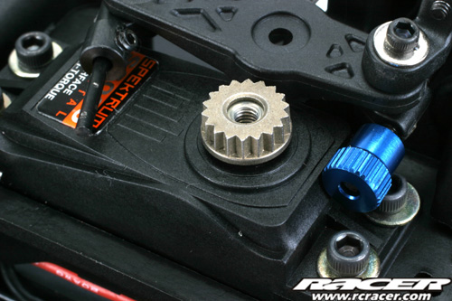
| Metal splined inserts interface with the composite kit servo horns. | The 23 spline part is correct for the Spektrum servos. Alternatives are provided in the kit for other manufacturers. |
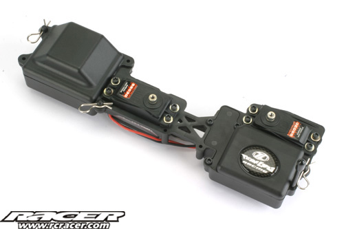
The completed radio system installed, ready to be attached to the chassis.
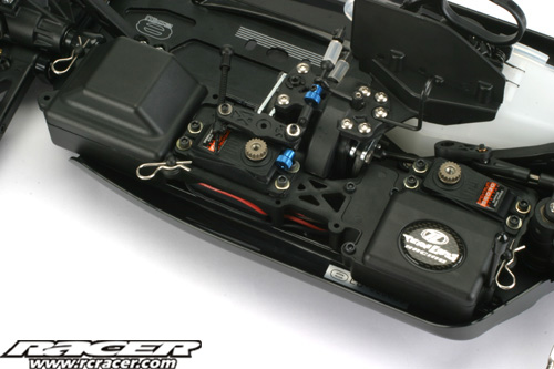
Step F-08 (10.10am)
Next up, the radio tray is attached to the chassis.
F-09 & F-10 (10.22am)
Finally for the radio, all that is needed is to hook up the servos to the linkages.
Step G-01 (10.35am)
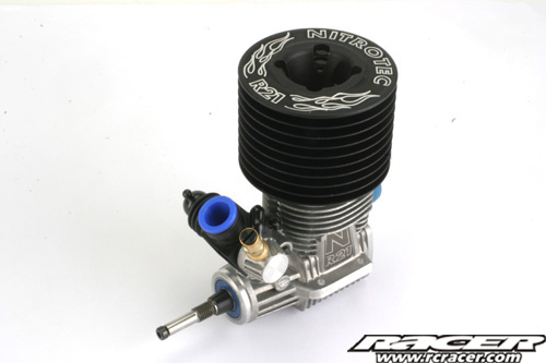
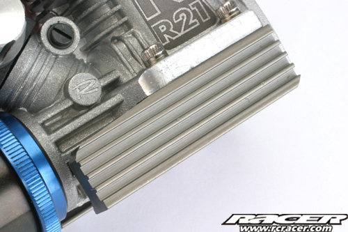
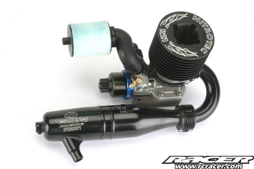
The G parts bag includes the parts that deal with the engine installation. Here we are using a Losi Nitrotec powerplant.
 |
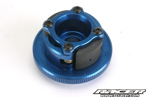 |
| Losi’s Nitrotec R21 is a full competition engine and a great companion to the 8IGHT 2.0 EU. | Losi’s clever clutch design means the shoes can be assembled to the flywheel before installation to the crankshaft. |
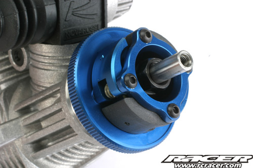
The clutch uses two aluminium and two composite clutch shoes. Make sure you use the kit collet to mate the flywheel with the crankshaft. This is a special half height part that gives the correct clearance for the clutch bell.
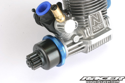
Step G-02 (10.40am)
Now the clutch bell is installed onto the engine. The clutch uses a larger inner bearing to help with reliability.
Step G-03 (10.48am)
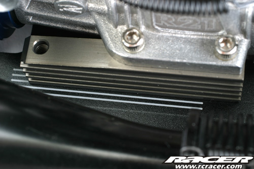
Step G-03 deals with the engine mounts and exhaust. Being a competition kit, you will have to source your own tuned pipe.
 |
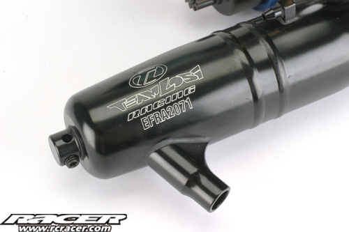 |
| The EU’s engine mounts are machined aluminium parts incorporating fins to help cooling. | The Losi tuned pipe we used is a quality item and EFRA homologated for competition use. |
Steps G-04 and G-05 (10.56am)
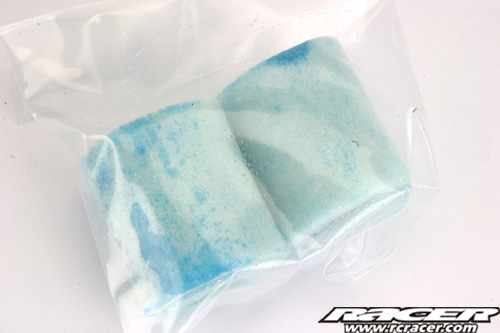
Now that we have a way of getting the gases out of the engine, best we filter the air that goes in! The kit includes an air filter and these two steps deal with its assembly and installation.
 |
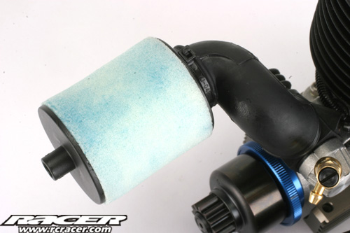 |
| The EU kit includes pre-oiled air filter elements. Losi even provide you with a spare. Which is nice. | The assembled air filter on the engine. The filter uses two separate foam elements. |
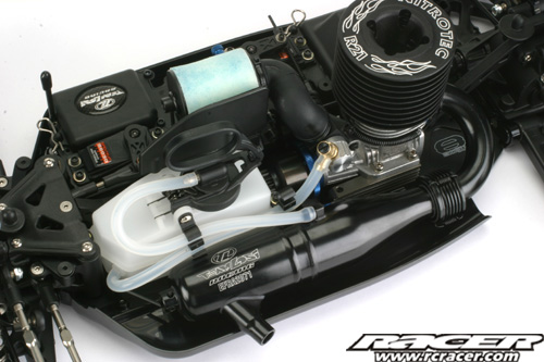
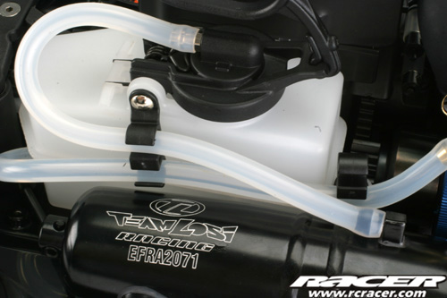
Steps G-06 to G-08 (11.09am)
The final stages of the G’s sees the engine assembly joined up with the buggy, and the fuel pipes attached.
 |
 |
| The fuel tank comes with these fuel pipe clips to help keep everything neat and tidy. | Marks etched on the chassis help you to install the engine straight and true. |
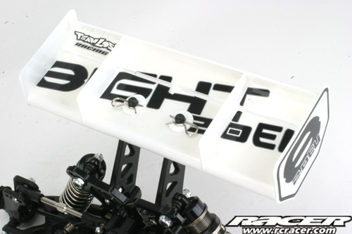
Steps H-01 & H-02 (11.15am)
The H steps are simply attaching the wing. The kit includes three sheets of decals, one of which includes some pre-cut ones to fit the 8IGHT’s distinctive wing design. These were duly slapped on and the wing held in place on the mount with body clips.
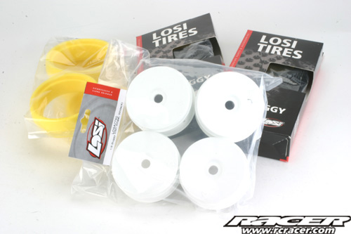
Finishing Up… (11.44am completed)
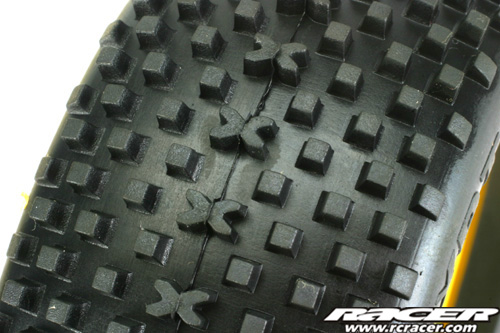
Thats it for the manuals construction stages, all that remains is to fit your choice of wheels and tyres and paint up and fit the kit included bodyshell. We again used Losi items for the wheels and tyres. I haven’t glued the tyres on for the pictures yet as my tyre gluing isn’t the neatest, and would end up looking like I did them in the dark while wearing a comedy seal flipper glove.
 |
 |
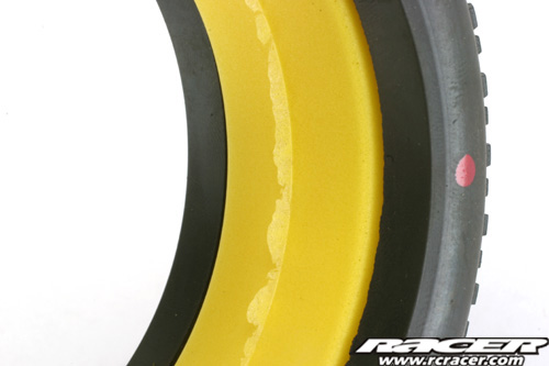
| Losi yellow compound inserts were used in the tyres. | The closed, lightweight and serrated wheel nuts are a classy touch on the EU. |
Bodyshell
The 8IGHT EU comes with a revised design of bodyshell that has a ‘shark fin’ on the back. Window masks are provided and our body was entrusted to RichPaint to show off the shell’s lines.
 |
 |

Build Conclusions…
The Losi 8IGHT 2.0 EU is without a doubt a quality piece of kit. Made to fine tolerances, the kit goes together superbly, no filing, trimming or shimming needed anywhere. It gives the impression almost that if you shook the box hard enough – it would build itself! What makes it good though is that it is a proven performer. The parts quality is as good as any other 1:8 buggy kit out there and surpasses the competition in some areas. But there is more to the buggy than the kit itself, the build manual is the most comprehensive seen from anyone giving loads of valuable setup information so you can get the best of the buggy. Also, the kit includes a bag of optional parts. With other manufacturers, these would all be additional cost but not with the EU. In the bag there is a green spring set, alternative anti-roll bars, shock pistons in different sizes and inserts to adjust the geometry. It really is a one box solution regarding a quality kit to go 1:8 nitro buggy racing with.

Downsides…
Only one….I now have to pass the 8IGHT EU over to Matt for a full Thrash Test review in Racer magazine! The Losi 8IGHT 2.0 EU is a polished package for sure. The buggy is innovative and would be top of the tree on my choices for an eighth off-roader, just on build quality alone.
Look out in a future issue of Racer magazine for the full Thrash Test. In the meantime, for more info on the Losi 8IGHT 2.0 EU visit www.horizonhobby.co.uk or www.losi.com
Also check out our gallery section here on rcracer.com where all the build images are located in full size versions.