Build Report – TLR 22
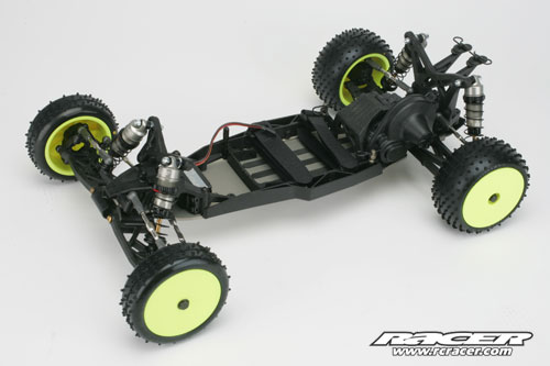
The rolling chassis is now complete with the body away to be painted and the electrical components waiting to be installed

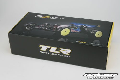
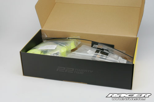
Racer is very proud to have received one of the very first samples of the TLR 22 2WD buggy from Horizon Hobby UK and will be building it up online, updating the website as the process develops.
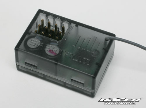
We have managed to secure top-spec electronic components including a Spektrum DX3R Pro radio with matching 2.4GHz micro receiver, S6070 low profile servo…
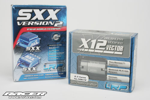
…LRP SXX Competition speed controller, Vector X12 6.5T motor and one of the very latest 3/4 length 3800mAh LiPos from Xcelorin, developed especially for use in 22 chassis.

Step A
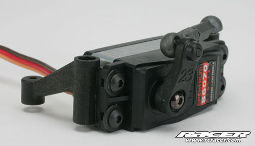
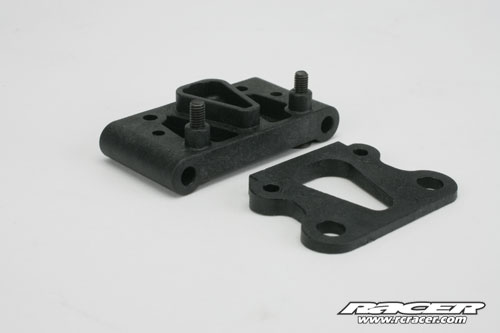
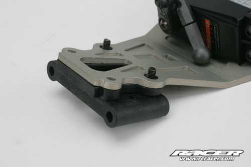
The first stage is to fit the servo mounts and servo arm. The moulding to hold the servo in place has two fixings each side to increase the rigidity of the mounting
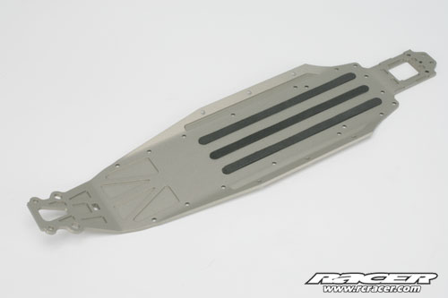
Next up is the alloy chassis and we stuck the three adhesive foam strips in place. These will help prevent the LiPo battery from moving in use
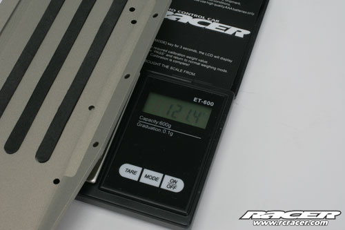
We decided to weigh the chassis to see how heavy it was…
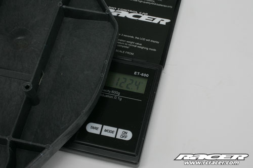
…or not as the case maybe! This is a moulded chassis for comparison. We didn’t include the moulded sides on the alloy chassis but for reference, each weighs just over 14g and this includes the alloy body mount at the rear
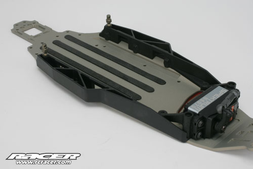
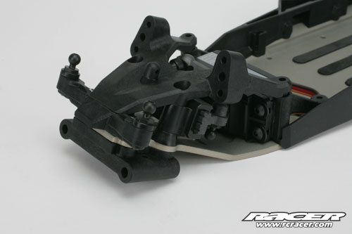
The moulded sides and servo could then be installed and the attention now moves onto the unique steering set-up and front bulkhead module.
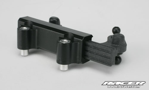
The steering rack on the 22 is simplicity in itself with just two plastic moulded parts. Although the darker moulding looks like its made from metal, it is moulded plastic but clearly a different make up the grey one. The only moving part of the steering rack is the grey piece and this includes grooves that are designed to ensure dirt doesn’t bind the mechanism
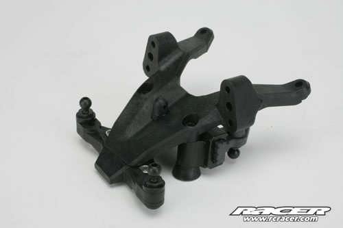
The steering assembly is then bolted to the front bulkhead along with what TLR call the camber block
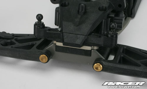
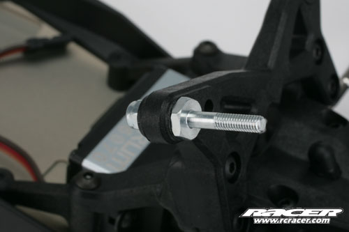
The kick-up moulding locates on the pivot block and the 20-degree option is standard although alternatives are supplied in a package with other tuning parts
Although there is kick-up on the chassis, a moulded spacer is used to set the angle at which the hinge pins work from. The two parts, pivot block and spacer are keyed so they lock into each other and then finally into the chassis. The screws then tighten into the front bulkhead
The plastic mouldings sandwich the alloy chassis
Just like previous 2WD buggies from the company, the 22 features a live axle for the front wheels
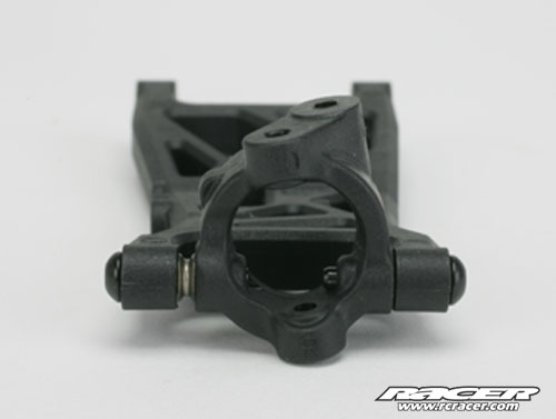
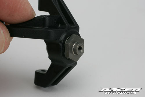
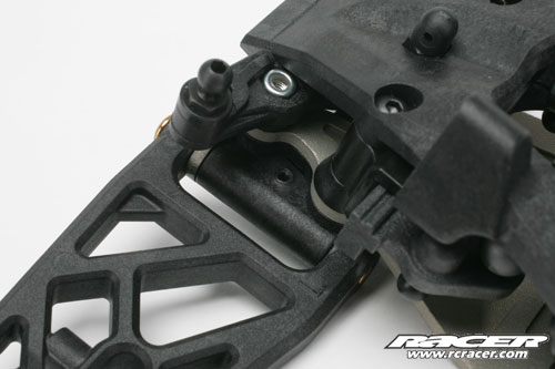
The caster block is a 10-degree item and with 20-degrees kick-up, gives a final caster angle of 30-degrees. Note the position of the caster block can also be altered within the front wishbone
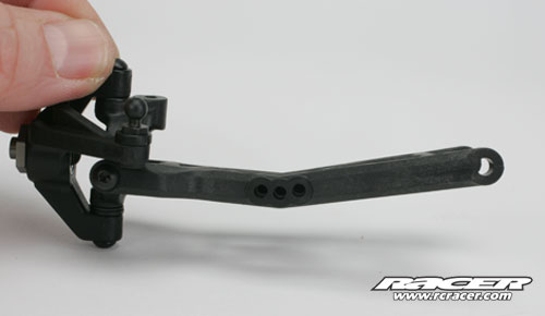
The completed caster block and steering arm
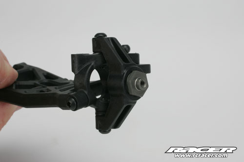
The caster blocks, like the steering arms could be off a 4WD chassis with this hole for a driveshaft to pass through….
Gull-wing shaped wishbones feature front and rear
Titanium Nitride-coated hinge pins pass through an alloy plate…
…and are retained with a grub screw from the top – no E-clips here
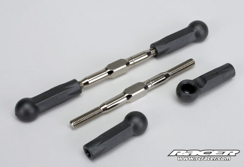
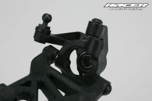
The turnbuckles are next up. The ball joints are new as they are not only bigger but metric. The turnbuckles are steel with a polished finish
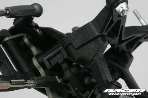
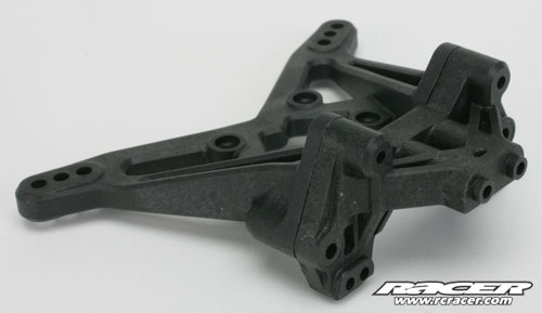
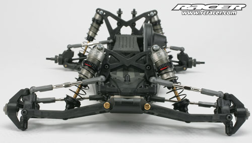
The front shock tower wraps around the bulkhead for a really solid mounting
The shock absorber mountings on the tower are of the quick removal-type
The front bumper extends back and is shaped to flow into the chassis. Two screws at the front hold it in position and it locates into the chassis at the back where it meets the angled kick-up section
Step A is now completed and so our next installment will focus on the rear suspension
Step B
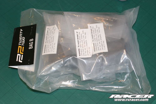
Many thanks for joining us today for the second part of our online build. Getting into the office early, the first job was to open the many plastic bags with the parts and fixings in. Step B contains the rear suspension including the wishbones, hubs, driveshafts, etc. There are some separate bags marked up “mid engine” and we found an alternative rear shock tower, rear bumper, camber block, and more. For the record, as this car will be run in the UK, it was only natural that we would build it in mid motor format…
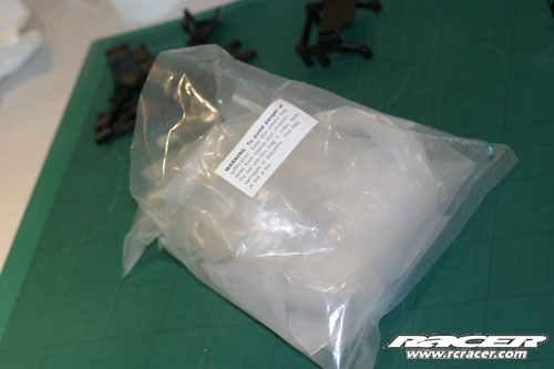
There are lots of bags within bags which we believe help with Quality Control, although these aren’t individually marked up. The picture above shows the bags just from Step B!
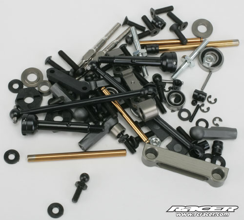
After opening all the bags, these were the small parts that will be used in this step
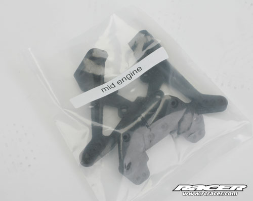
The dedicated mid-motor rear shock tower and camber block
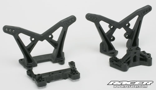
Ignoring the order in the manual, here is how the rear and mid-motor rear towers and blocks compare (mid is on the right). Note the camber block for the mid car gets flipped over to fit to the underside of the tower…
…like this. The mouldings are keyed so the parts locate perfectly
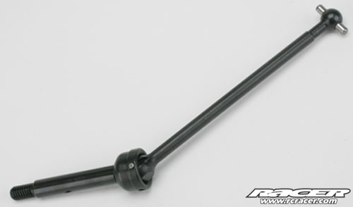
Back on track and following the manual, the driveshafts are the first parts to put together and these are of the standard universal joint-type. A grub screw holds the pin in the UJ section. We were very impressed with the weight of these UJs as they feel very light for steel
A Titanium Nitride-coated hinge pin on the inside uses a pivot ball to allow for free movement across the range of anti-squat positions
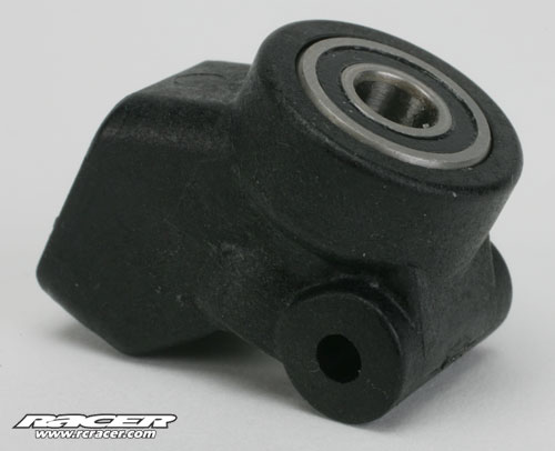
Rear hub features a bigger outer bearing than inside for greater strength and better durability
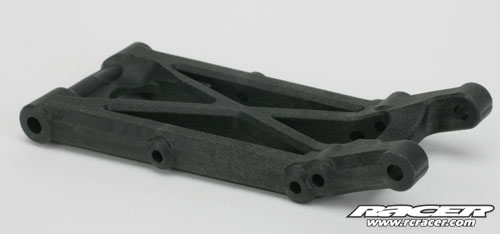
Like the front, the rear wishbones feature a kicked-up end
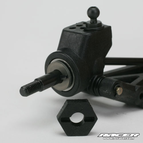
With all the parts in place, the driveshaft can be inserted. The 22 drops the popular pin-drive arrangement for a hex to the wheel that offers greater surface area and more suited to today’s high-power brushless and LiPo systems. It is also a system that makes it easier to locate the wheel properly, unlike a pin that can “make” its own as we have found
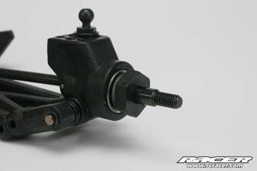
Here is the hex adapter in place. This was a little tight so we place a little chamfer on the hole to help
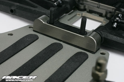
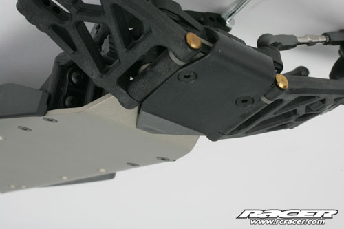
With the rear wishbones equipped with hubs and hinge pins, the parts can be fitted to the chassis. A 1-degree anti-squat shim is placed under the front alloy pivot block. The moulded insert that the screws pass through is dedicated for the mid-motor chassis. The long screws are used to hold the pivot block in place during construction, and we used the nuts off the shock tower mounts to clamp it on place as the anti-squat shim has a tendancy to slip out
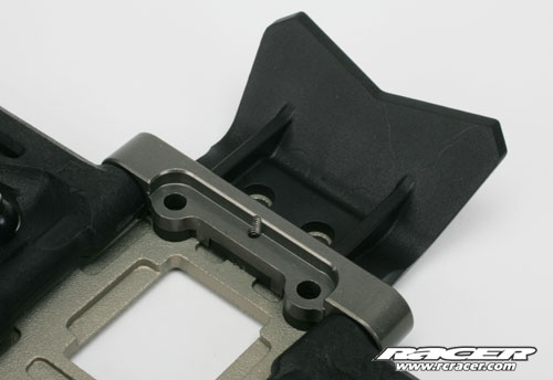
The rear bumper locates under the rear bracket and a very small counterunk screw in the centre holds these in place for the time being
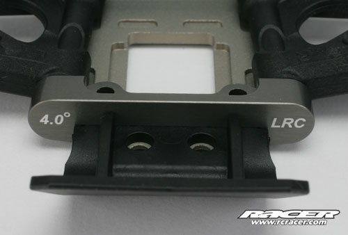
The kit comes with a low roll centre (LRC) and 4-degree toe-in block although a high version will be available from the option parts list
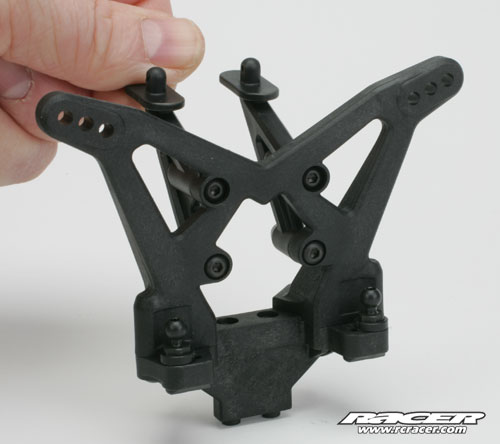
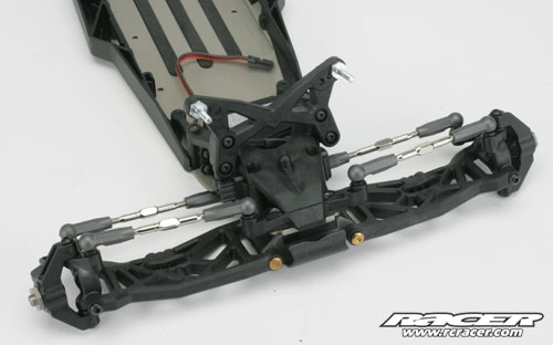
The wing mounts and camber block are screwed to the rear tower before the assembly can be mounted to the chassis
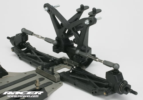
With the tower in place, the camber links can be snapped into position and this completes Step B
Step C
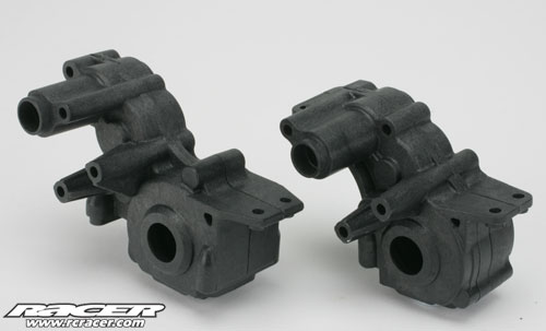
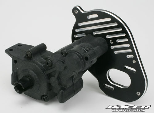
The third stage of the build is the gearbox and with the option of a rear or mid-motor set-up, TLR include two gearbox cases to suit each application. The four-gear (mid-motor) is on the left and three-gear (rear-motor) is on the right
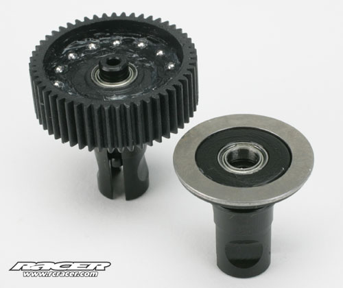
The diff of course is the same for both an this features flattened plates and hardened balls. The diff features the minimum number of parts so there are no shims or washers to lose. A spring is used to tension the diff bolt and the latter is held by a nyloc nut in a carrier so can easily be replaced
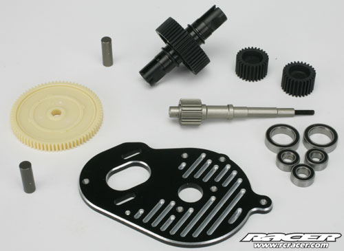
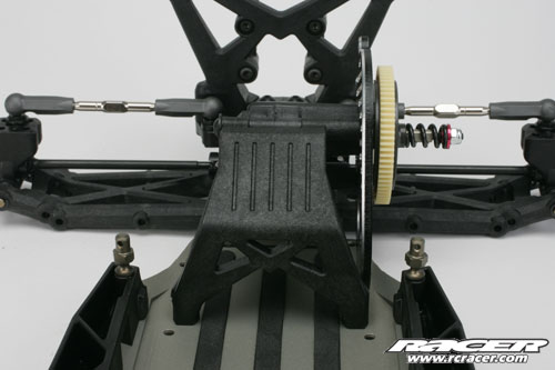
With the diff built, we dragged out some of the other components needed for the next stages of construction. The spur gear is a 76T item and uses the proven double pad slipper clutch arrangement. The layshaft is one-piece alloy and is coated for efficiency and good wear characteristics (as are the idler shafts). The gearbox rotates on a full set of bearings and the same bearings are used on the layshaft and idler for a really neat set-up. The motor plate is machined as standard and the same one is used for both gearbox options
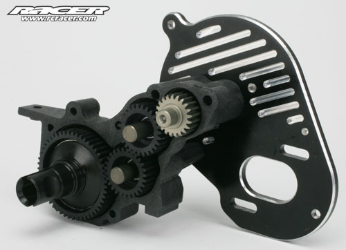
The gears being located in the casing
The gearbox is now complete and all bolts were tightened with no sign of any binding or need to back off any of the fixings
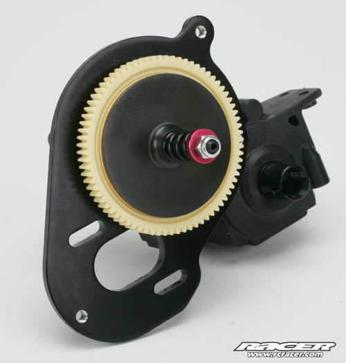
On the opposite side is the dual pad slipper clutch. Not sure why TLR chose red of the alloy spacer (behind slipper back plate) and the shaped washer at the end of the shaft?
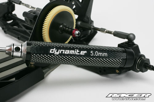
We found out the thread on the layshaft uses a 2.5mm thread and therefore a 5mm nyloc nut. Dynamite offer a really nice machined 5mm nut driver that we sourced from Horizon Hobby UK. We would suggest getting a spare nut or two for your pit box as this will not be something you have lying around. It’s also worth replacing this nut regularly for a really good hold of the slipper clutch setting
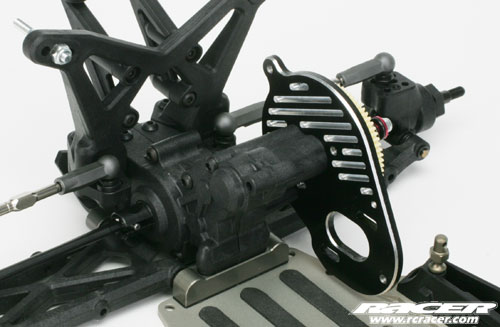
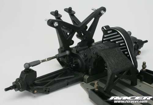
The gearbox can then be fitted into the chassis using six screws. The manual threw us a curve ball here as it suggested using another two screws for the front fixings. As there were two of exactly the same spec holding the pivot block in place already, just use them – something to bear in mind when you find that there are two left over!
Next up is the rear chassis brace moulding that drops into position and is secured from the side and below
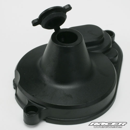
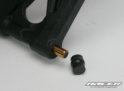
The gear cover follows and this features a neat bung retaining system that will prevent that small item ever being lost again!
This now completes Step C and its the shock absorbers up next and Step D which we will do tomorrow (Wednesday). We will also complete the build with the battery tray and straps, wheels and ancillaries
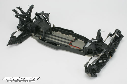
This is how the chassis looks now
Step D
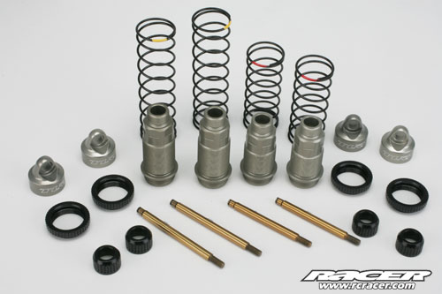
The shock absorbers follow the proven design of the TLR 8ight 1:8 off-road buggy and here are the main components. Threaded bodies, Titanium-Nitride-coated shafts, alloy adjusters, alloy seal retainers and coated springs. Not shown are the four-hole pistons and rubber diaphragms – the former are held in place by an E-clip either side
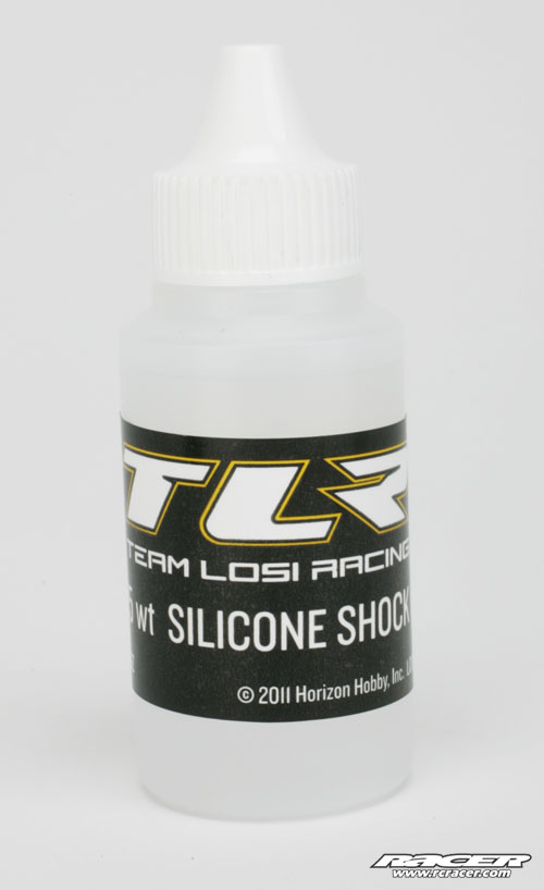
TLR supply a large bottle of 27.5wt oil for both the front and rear shock absorbers – the big picture above wasn’t intentional, but it is ironic!
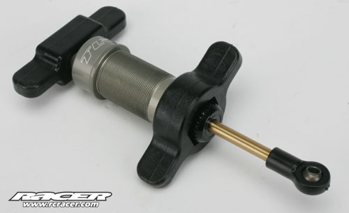
A moulded tool set helps to build the shock absorbers – the process is incredibly simple and with the bleed hole in the cap, make sit impossible to over fill them with oil
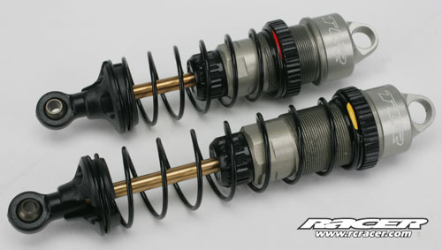
The springs are all black in the kit and will be the same for the ones on the options list. The spring rate is indicated by a splash of colour at one end
Our 22 is very nearly there with all four shocks fitted and ready for the final bag to opened. The final bag for Step E of the build contains the fluoro yellow wheels – you get two complete sets in the box – Velcro battery straps, body clips, wheel nuts and some other small parts. For the record, there is a sixth bag that includes some optional pieces like anti-squat shims, optional kick-up mouldings, alternative pistons and more
Step E
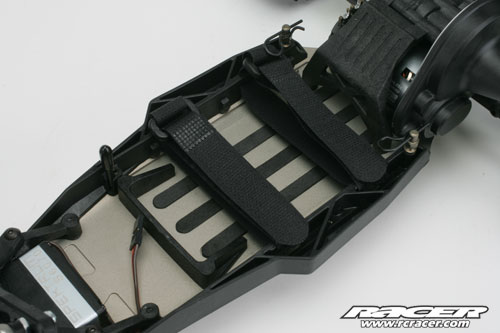
Velcro straps are used to secure the LiPo in place along with the moulding at the front. As we are using the Xcelorin short LiPo, we can position it there and then squeeze in the LRP speed controller and Spektrum receiver between the moulding and Spektrum servo. Of course regular saddle pack LiPos can be fitted in mid-motor format and in rear configuration, there is even more of space
![]()
TLR logo features on the outside face of the new design wheels. We fitted Schumacher Mini Spikes to the wheels along with their foam inserts
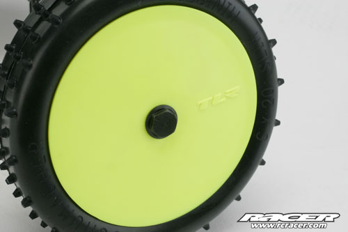
The front wheels are held on by a bolt with a 7mm head – the same as the rear. Whilst the rear nuts feature a locking insert, the fronts don’t so place a drop of threadlock on the thread of the bolt, then let it dry before fitting
And there it is, the completed TLR 22 minus the body that is being painted as we speak by Dave Holmes of Custom Graphics
Summary
To sum up, the 22 is very nice to build and is packed with the flexibility to suit global track demands and the driver’s preferences. The chassis re-ignites the passion of old Losi fans and wraps it up under the new TLR banner very neatly. There is so many new ideas and features on the 22 that I am glad it’s a TLR product and not a Losi one. The new TLR brand suits the 22 perfectly and the final product is a credit to the team that has designed, tested, developed and manufactured it. Of course the real test will be on the track and in the hands of the paying customer. As I write this, the first batch of retail-bound kits are being processed at Horizon Hobby UK along with the spares and option parts. In our magazine review published in the June 2011 issue of Racer, we will have had a chance to give the thoroughly test the car and will run through some of the best options available from the list.
Many thanks for taking the time to read our online review and if you have any comments, please pass them on to me at web@rcracer.com where I would appreciate any comments. Until next time…
Racer would like to thank to all that have helped us with this online build including:
Horizon Hobby UK (www.horizonhobby.co.uk)
TLR 22 chassis/Spektrum DX3R Pro transmitter/Spektrum SR3500 micro receiver/Spektrum S6070 servo
LRP (www.lrp.cc)
LRP SXX Competition speed controller/LRP Vector X12 6.5T motor
Schumacher Racing (www.racing-cars.com)
Schumacher Mini Spike tyres/Schumacher foam inserts
Dave Holmes at Custom Graphics
Body shell painting
Other useful resource links:
TLR (www.tlracing.com)
Spektrum (www.spektrumrc.com)