


How To Eliminate On/Off Switches
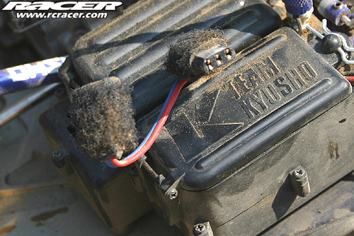
Have you taken a closer look at the 1:8 scale nitro chassis of pro drivers lately? If so you might have noticed that the majority of them uses high current plugs over conventional on/off switches. Why is that?
The constant vibrations created by a nitro engine as well as dust, dirt and moisture can harm the often delicate switches and therefore high current connectors like Deans and many others can make for very high reliability even under the rough conditions nitro off-road racing has to offer.
If you are a regular reader of Racer magazine you might have noticed that we always replace the four cell battery holders supplied with the radios or RTR cars and trucks with proper five cell packs. This adds safety as well as a bit of extra performance for the steering and throttle/brake servo. To further add to this we advise to use high current connectors to replace the fragile switches that are harmed by dust and moisture very easily. Even the silicone guards that are offered as aftermarket parts do not protect them 100 percent.
With this ‘How To’ we want to show you how easy it is to replace that old and worn switch with some proper connectors. The green connectors shown here are from German company Multiplex but you can use any high current connector you can think of to create a bullet proof connection between the receiver battery and the receiver. Off we go!
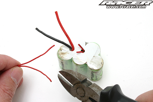
Our five cell battery pack came with two thin wires to plug it into the receiver as well as with two thicker wires to charge it when built in. We cut the thinner ones off and only used the thick ones.
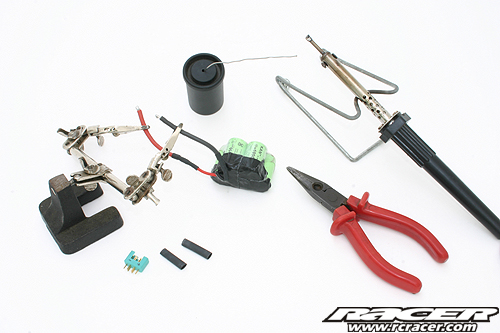
This is what is needed to change your now useless switch for a nice set of connectors.
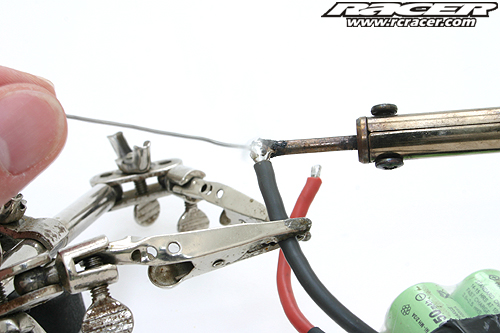
Tin the ends of the battery wires.
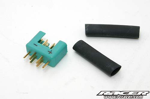
There are loads of good connectors on the market. We used the green ones Multiplex. You can make use of Deans plugs or anyother high Amp connector of course.
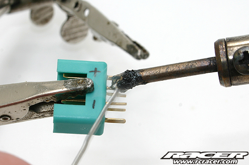
Tin three of the six poles for the positive pole and the other three for the negative pole. Other connectors like he ones from Deans for example only have one big solder tab per pole. Make sure your solder tip does not look as dirty as ours!
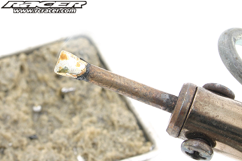
A wet foam cleans the tip. It should have a metal sheen like shown here for best results.
Only use a small amount of solder to tin the tabs.
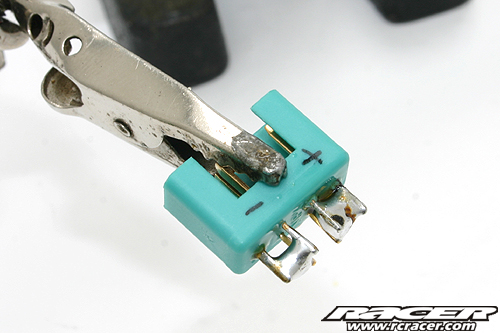
Positive and negative pole properly tinned.
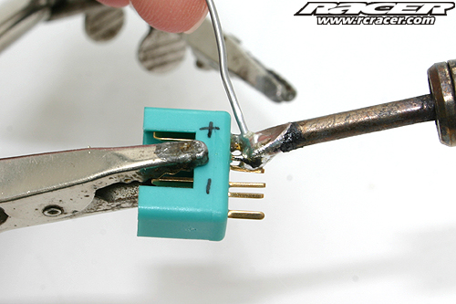
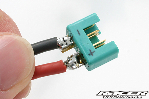
Do not forget to put the heat shrink over the wires BEFORE you solder the connector to the wire. Keep the shrink wrap as far away from the soldering tip to avoid it from shrinking before you need it to!
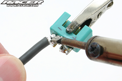
The positive and negative pole soldered properly …
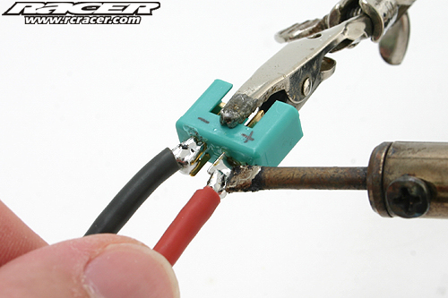
… with nice solder joints that have an even metallic sheen.
Broken or craggy solder joints are likely to break during operation. Try it again with a stronger soldering iron or different solder.
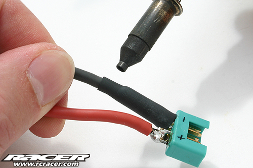
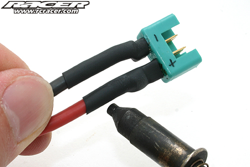
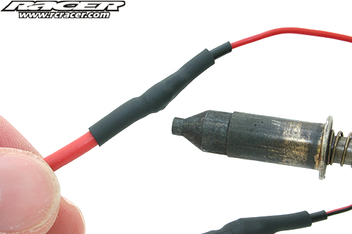
You can use a lighter, a heat gun or a gas-powered soldering iron like this one to shrink the heat shrink.
Try to find a shrink wrap with good abilities to shrink. Cheap ones often only shrink at rates of 2:1 instead of 3:1 which suits our needs better.
A larger heat shrink is used to cover the whole connector for added protection against dirt and moisture.
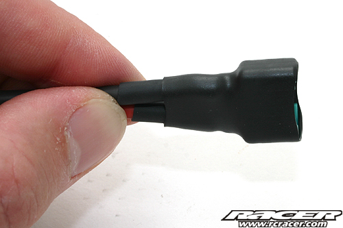
Now our battery has a nice high current connector on it. But as you know we are not after the high currents but the added safety when it comes to eliminate that darn receiver switch.
In our case we used the ‘male’ plug for the battery. Normally it is recommended to use the ‘female’ part as it has hidden contact tabs. This is important when you store the receiver pack in our pit case as metal parts could short-circuit the battery!
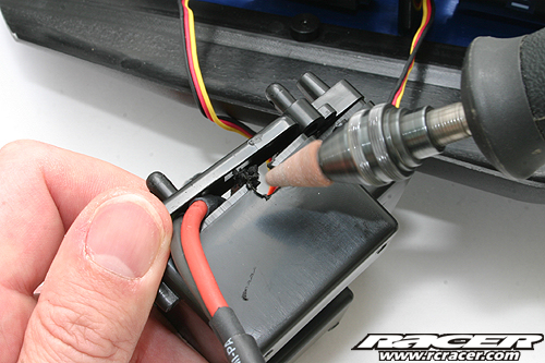
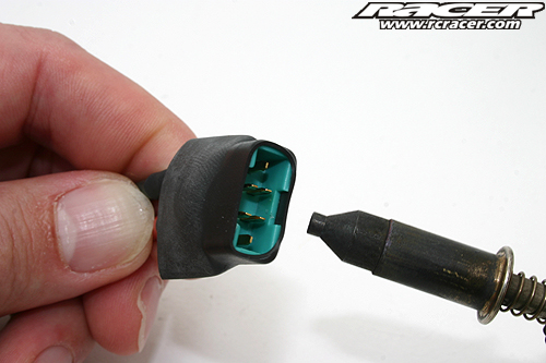
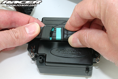
Depending on the design of the battery box of your car and the diameter of the wires you may feel the need to extend the cable channel on the radio box.
If you create a tight fitting between the box and the cable you can apply silicone to seal everything later.
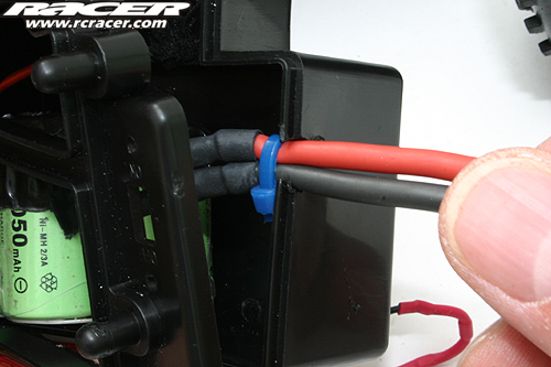
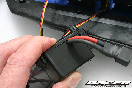
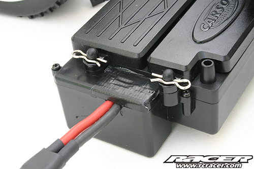
Use a cable tie to create a strain-relief to avoid too much stress on the wires when you disconnect the plugs in hurry. 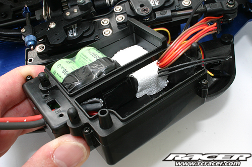
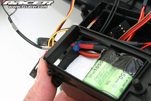
Make sure to secure the receiver and battery with foam to avoid them from rattling in the empty RC box.
Now the counterpart for the receiver lead has to be made.
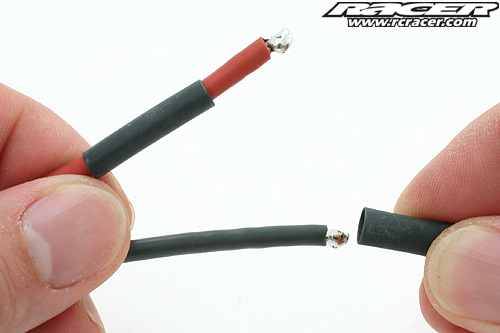
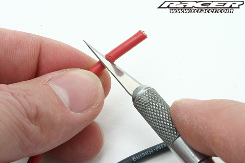
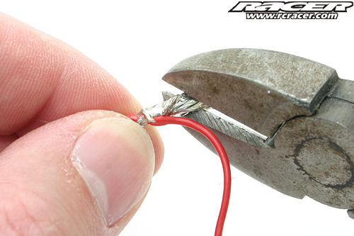
Use some 16AWG wire or similar and remove around 10 to 15 millimetre of the silicone coating.
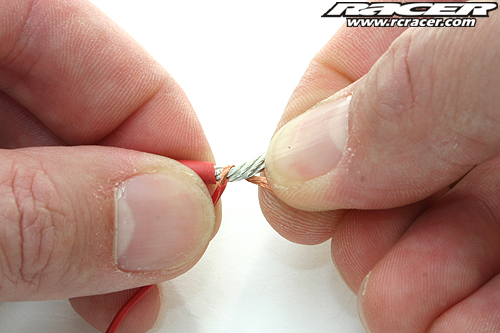
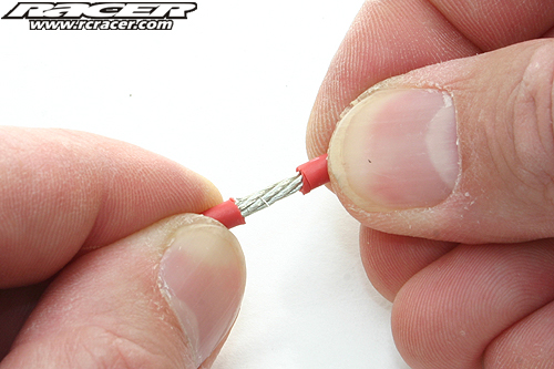
Now grab the cable that goes into the receiver (take it from the old switch) and remove the coating like you did before. Wrap the two red and the two black wires together.
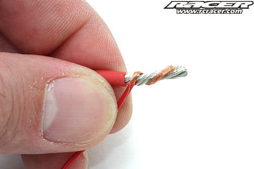
It should look like this.
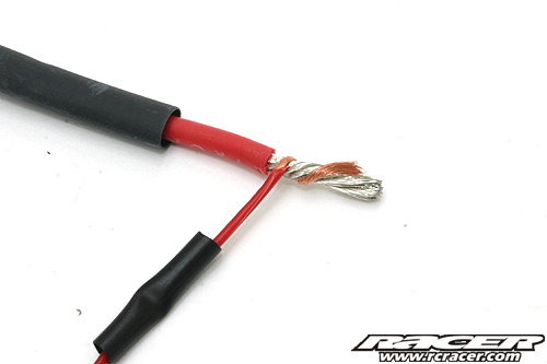
Don’t forget to pull heat shrink over both ends beforehand! Use smaller diameter ones for the thinner wires.
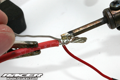
Solder them together thoroughly.
If the joint is a tad too long, cut it!
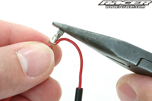
In case you shortened the solder joint even the cut with a file or pliers to make sure no sharp edges cut into the insulation or shrink wrap.
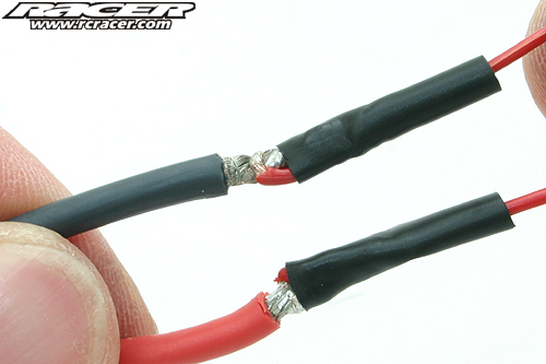
Now slide the thinner shrink wrap over the solder joint …
… shrink it …
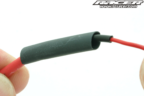
… and pull the larger one over the whole arrangement.
If both shrink wraps are positioned properly you end up with a very strong and durable connection.
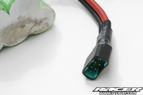
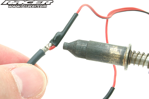
Our adapter is ready to be installed. Secure the ‘female’ side with large shrink wrap
as well to protect it from dirt and moisture. 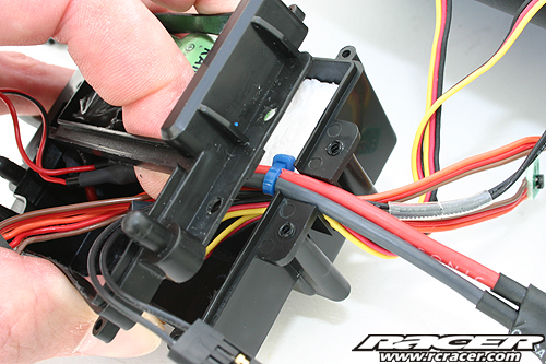
Once again a cable tie comes into play as a strain-relief.
Make sure the thick wires are long enough so the strain-relief attached to the sturdy wires and not the tiny cable of the battery or the adaptor.
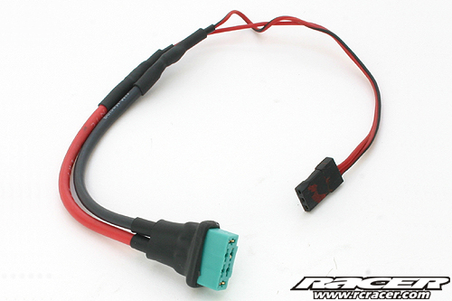
This is the result. A nice looking and strong yet easy to use connection.
Now seal the hole for the on/off switch with duct tape or use the plastic inserts that are supplied with many of the kits.
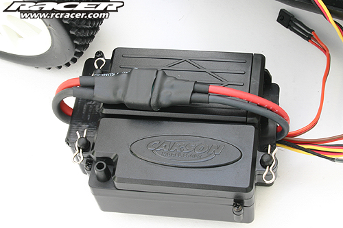
The modified RC box is ready to be installed in the chassis. Of course you can try and work on the box when attached to the chassis but we recommended to take your time and detach it from the chassis.


Very easy to follow directions on this must do mod on all RC cars. I have seen may racers like you chase after their RC buggy because these switches moved to the off position after a buggy has a hard landing, everyone know what could happen after. The good news is if you remove the switch you don’t have to worry about this happening to you.
Watch what happened to Ty Tessmann in the 2017 Dirt Nitro Challenge truck main… Using a plug instead of a switch IS JUST NOT WORTH IT….
He talks a bit about it here: http://www.liverc.com/news/race_results/14225-Tessmann_talked_battery_failures_in_DNC_race_report/
But that doesn’t convey just how crappy it was to see his track go FLYING off the track for no apparent reason. But we know now… it was all due to a plug very, very similar to the example in this “how to.”