Tamiya 4×4 Pick-Up Bruiser – Online Build Final Part
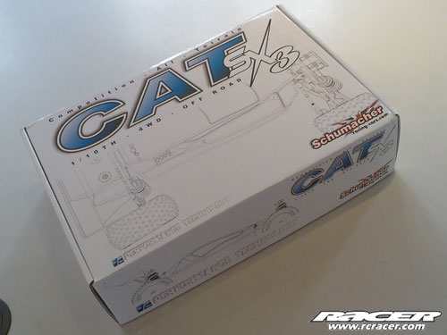
So this is it what many Tamiya RC fans have been waiting a very long time for, the re-release of the iconic Tamiya 4×4 Pick-Up Bruiser. In this online build, we show you the main features of the chassis, ahead of a reveal of the finished Tamiya 4×4 Pick-Up Bruiser in a future edition of the magazine.
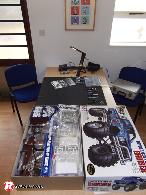
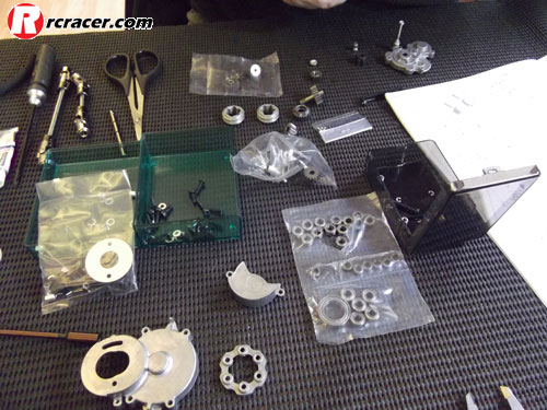
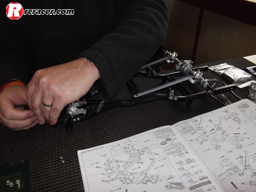
As you can see we have set out a large area here at the Racer Offices so we have plenty of light using our new Integy Pit Table Light and space to build this truck.
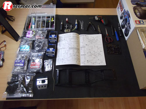
We have laid out the tools we think we will need and most of the items that we will require during the build. As with any Tamiya build the manual is very in-depth and works through each bagged section and we start with Bag A.
Bag A
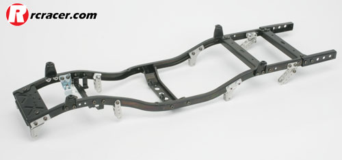
The start of the build sees you attach many of the shackles and carriers to do with the leaf spring suspension and the start of the steering mechanism. Each nut and bolt is threadlocked in place to ensure there is no chance of it coming apart whilst in use.
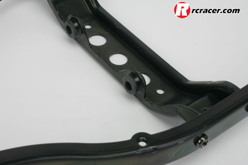
We did find that getting into some of the areas to hold the bolts in place was tricky with just the standard Tamiya box wrench, so a 5.5mm nut driver came in very handy. In this part of the build you will also need to insert the rubber O-rings and dampers into the chassis cross members to mount the gearbox onto at a later stage. Be careful whilst doing this so you don’t tear or damage the rubber O-ring.

One thing to be careful when installing the rear bumper hangers is that the alignment of all the holes is correct before final assembly; you may find you need to loosen other sections of the chassis to allow enough flex to get the correct alignment.
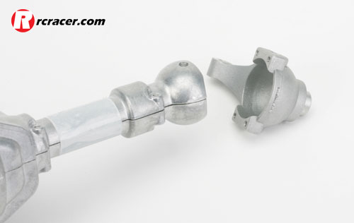
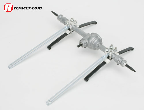
Bag A also contains the main components for the both axles. There is a supplementary instruction inside the book that shows you how to deal with excess material around the axle casings so that the steering knuckles can move with ease. Luckily our axles didn’t have this major issue so with a small amount of filling we could move on with the build and start to fill the axle with the necessary gears and output shafts.
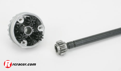
The differentials require a fair amount of concentration if you have never built one of this style of diffs before as there are two groups of opposing planetary gears three up and tree down. And two central output crown gears.
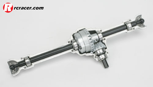
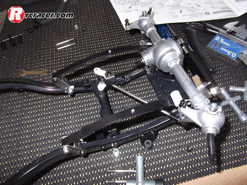
This is the front axle sub-assembly (below).
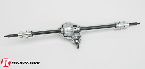
The rear axle sub-assembly is shown below.
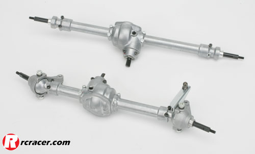
The build of both axles is fairly symmetrical and build very quickly and easily once again ensure you use threadlock on all bolts.
Bag B
Now we move onto the suspension part of the build.
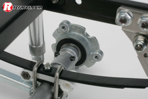
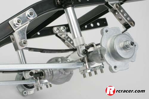
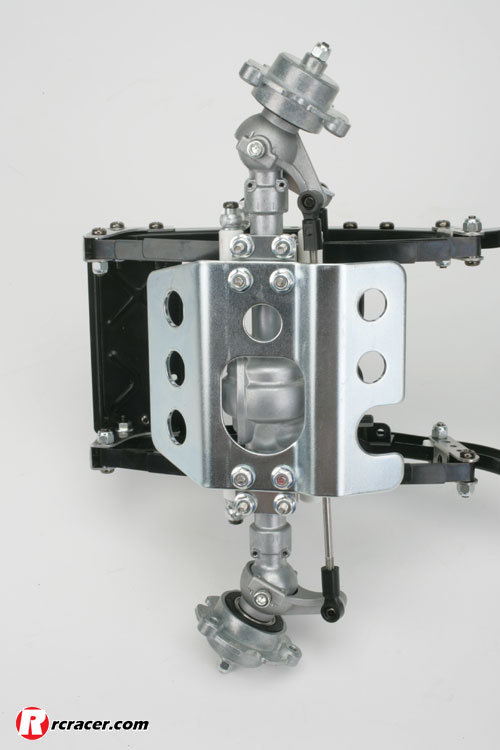
 In this section, the leaf springs are built up as well as the trailing arms for the rear axle, which is are attached to the axles via U-shaped bolts that are captured through small metal axle housings. You must ensure that the U-shape bolts are tightened equally otherwise the axles will not sit correctly.
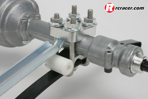
The front axle is held at a 5-degree angle which Tamiya show you how to get correct in the manual whilst the rear axle is held at 0-degrees. This is to allow the correct angle for the propshafts in a later step.
When it came to installing the front axle, we found that during construction we had accidentally rotated the springs around the axle housing by 180-degrees, which was a simple fix although a little time consuming. 
It was also at this point that we had realised another mistake. 
In the rush to build the leaf springs, we simply got the sandwich of the three springs reversed.
 Again this was a time consuming fix so before we commenced onto the build some more it was time for coffee and lunch!
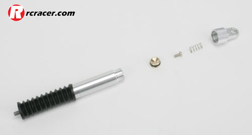
The final stages of Bag B deal with the building the dampers, these are fairly fiddly are need nimble fingers with the aid of some needle nose pliers. Damper oil is included with the kit and the dampers have a built in bleed valve in the free piston so you can get perfect damping action with little fuss. The top cap has a spring underneath it which keeps the free piston in place. The free piston acts like a diaphragm on a regular shock absorber.
Next up are the wheel hubs this simply need the plastic spacers for the bearings inserted and then the bearings inserted inside those, these are then fitted to all four axles.
The connecting rod which attaches the two steering knuckles is then put into position.
And finally all four shock absorbers are positioned onto the frame and the front axle gets a protective shield.
Bag C
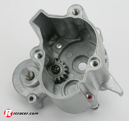
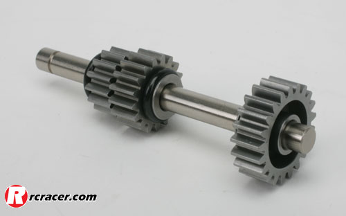
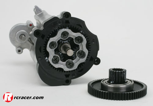
This is the part that strikes fear to even the hardened builder. Tamiya’s three-speed gearbox is a sight to behold. Containing no less than 28 ball raced bearings, the instructions need lots of careful attention to make sure you build the gearbox correctly and ensure smooth shifting action.
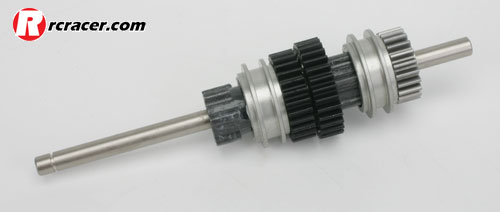
Since the original Bruiser, Tamiya have refined the gearbox to ensure smoother shifting and to also make sure it is capable of handling today’s powerful motors.
 We are very thankful for Tamiyas 1:1 parts listing down the edge of the manual as this is a great reference to have when searching for the correct spacer and gear. 
Don’t forget to grease all the points that are pointed out on the manual.
The first half of the gearbox build houses the three-speed selector mechanism and transfer box. This is rather fiddly again with several parts having to be juggled around and held steady. The trickiest bit is the shift release mechanism where two ball bearings are held in the selector mechanism. We almost lost these whilst taking the shots of the gearbox build, although Tamiya supply plenty of spares should you lose them.
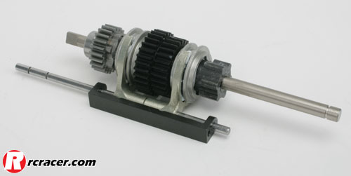
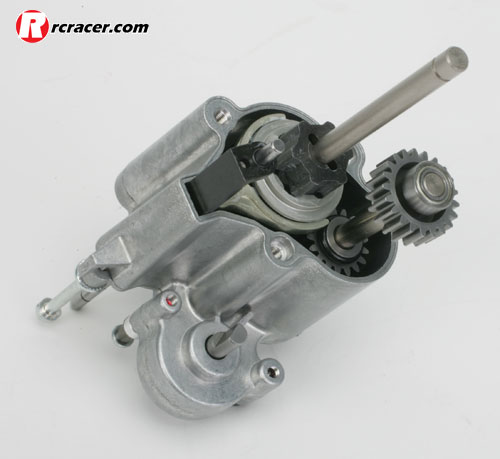
The second part of the gearbox holds the planetary gear diff and motor housing, which when compared to the first half build goes together with relative ease.
 One thing that Tamiya have done is to include a complete spare set of plastic gearbox internals should you damage any in use.
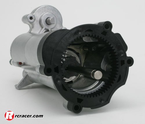
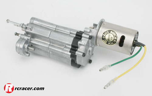
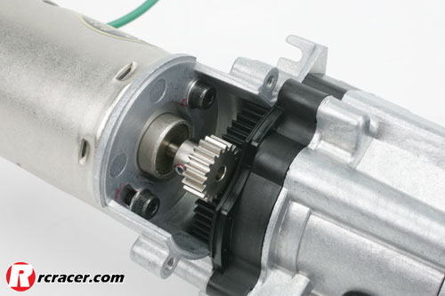
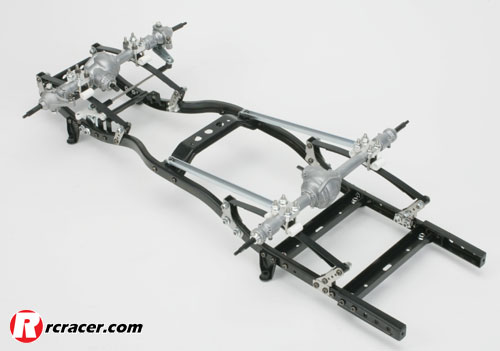
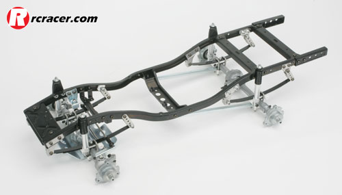
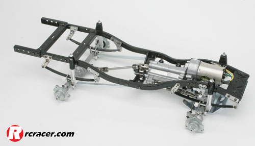
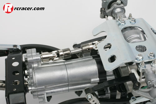
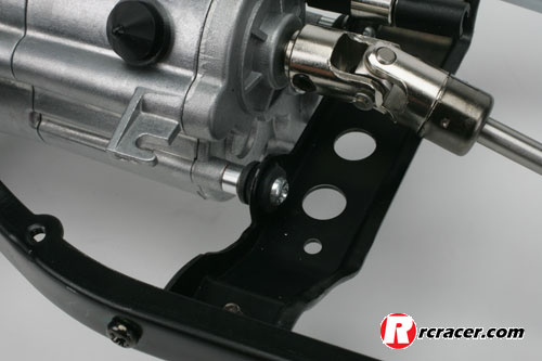
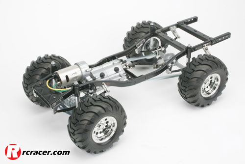
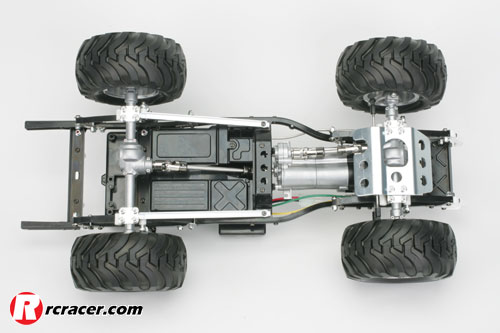
The entire gearbox assembly is then slipped into the chassis and the propshafts are now connected to the front and rear axles.
Bag D
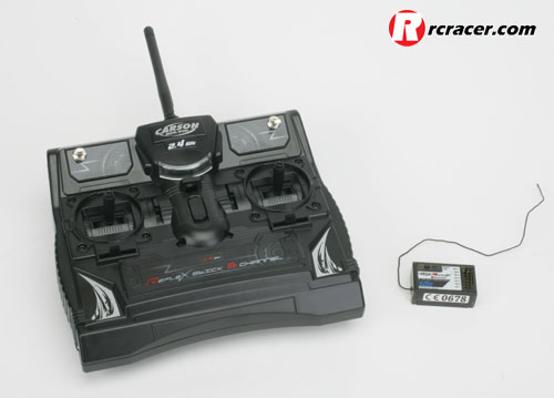
Now we move onto the control mechanisms and for this build, we had been supplied with a Carson six-channel tray-style radio. This may not be everyone’s cup of tea, but it’s ideal as it has a three-position switch on channel six that allows you to choose the which of the three gears you want with just a flick of the switch.
 The controls do take a little getting used to however, should you choose to, the Bruiser can be built with the gearbox locked in a chosen position for using with a two-channel radio system.
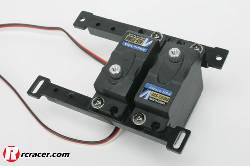
The servos are the first thing to find a home and for this Logic supplied us with two of their Alturn AAS-750MG servos that have a torque spec of 9kg so should keep the Bruiser pointing in the right direction. We also used the same on the gearbox, possibly a little overkill but better to be safe then sorry when your transmission won’t shift.
Both the steering servo and shift servo are back upped by Tamiya’s own design servo saver to ensure that the servos cannot get damaged should either mechanism get stuck.
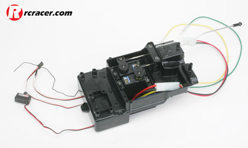
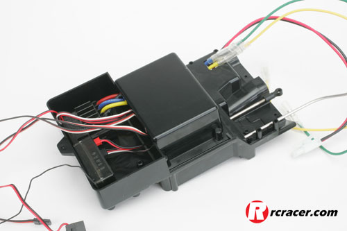
 All the radio gear is housed on the rear of the chassis in a plastic radio tray designed to take all the components and builds up fairly easily. When completed it can be removed from the Bruiser to enable easy cleaning in moments by removing four screws holding it onto the chassis rails. 
The radio tray also houses the battery bracket that is now reconfigured to take a standard stick pack or LiFe battery should you wish to do so.
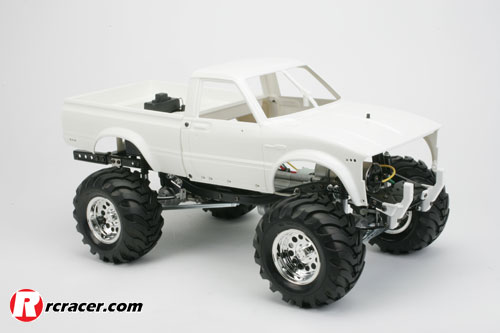
Whilst the radio tray was being built, we decided it was time to put the wheels on to really give the Bruiser some muscles to flex. 
These hold onto the hubs with three bolts per wheel much like your normal road going car, so there is not much chance of a broken hex in the Bruiser as there aren’t any to break!
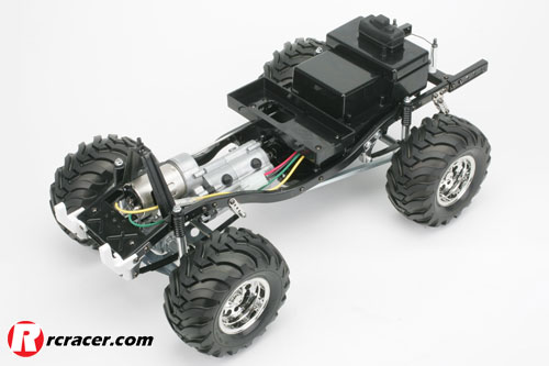
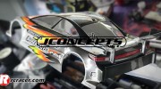
Bag E is used for the body and you can see the finished item in Racer Magazine. But we couldn’t resist sitting it on top to take some shots to see what the finished item will look like.
Thank You
Racer would like to thank The Hobby Company and Logic RC for their help with equipment and Stef Godfree for assisting with the build.